Micro lens array sheet for use in backlight device and molding roll for manufacturing such mirco lens array sheet

a technology of mirco lens array and micro lens array, which is applied in the direction of dough shaping, manufacturing tools, instruments, etc., can solve the problems of generating luminance unevenness, reducing the useful life of molding rolls, and substantially impossible to place micro lenses in contact with each other

Active Publication Date: 2009-10-01
MAXELL HLDG LTD
View PDF2 Cites 24 Cited by
  • Summary
  • Abstract
  • Description
  • Claims
  • Application Information

AI Technical Summary

Benefits of technology

[0014]In the molding roll according to the invention, the peripheral edge part of the lens forming hole is rounded, so that the above-described micro lens array sheet can be manufactured. Fu

Problems solved by technology

However, when a micro lens array sheet is produced by the roll-to-roll method, it is substantially impossible to place the micro lenses in contact with each other because the edges of the lens forming holes on the molding roll must be in contact with each other in order to place the micro lenses in contact with each other.
In this case, the edges of the holes on the molding ro

Method used


Image

  • Micro lens array sheet for use in backlight device and molding roll for manufacturing such mirco lens array sheet
  • Micro lens array sheet for use in backlight device and molding roll for manufacturing such mirco lens array sheet
  • Micro lens array sheet for use in backlight device and molding roll for manufacturing such mirco lens array sheet

Examples


Embodiment Construction

[0025]Now, an embodiment of the invention will be described in detail with reference to the drawings, in which the same or corresponding portions are designated by the same reference characters, and their description will not be repeated.

[0026]1. Micro Lens Array Sheet

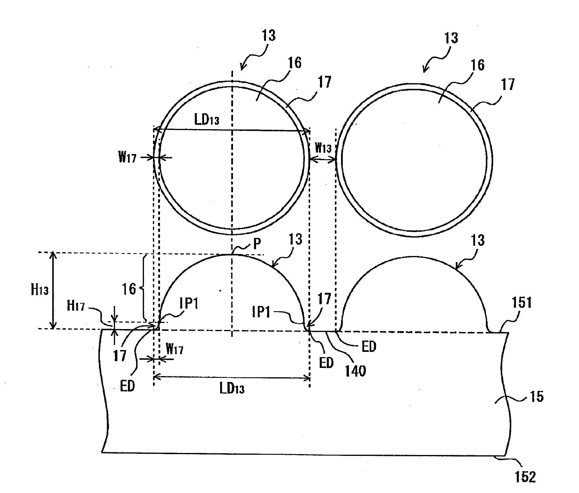
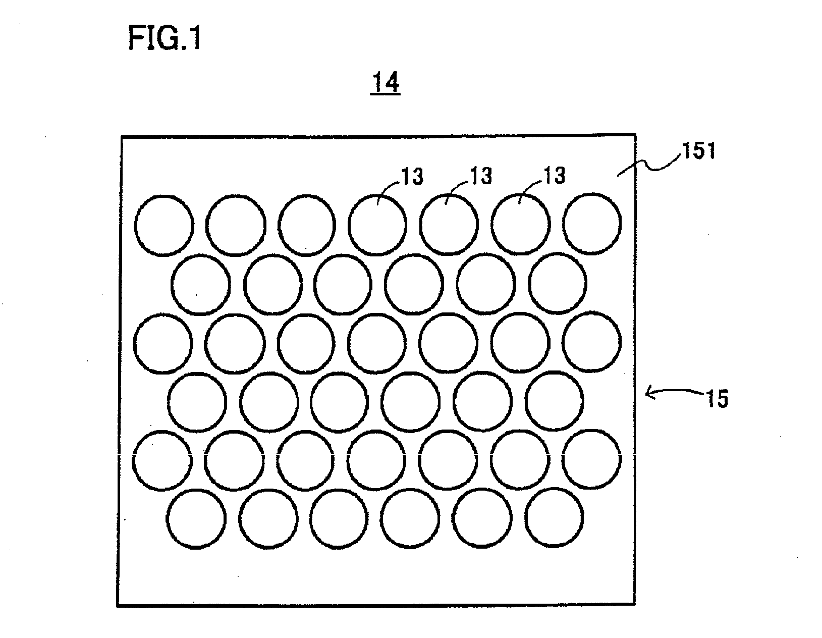
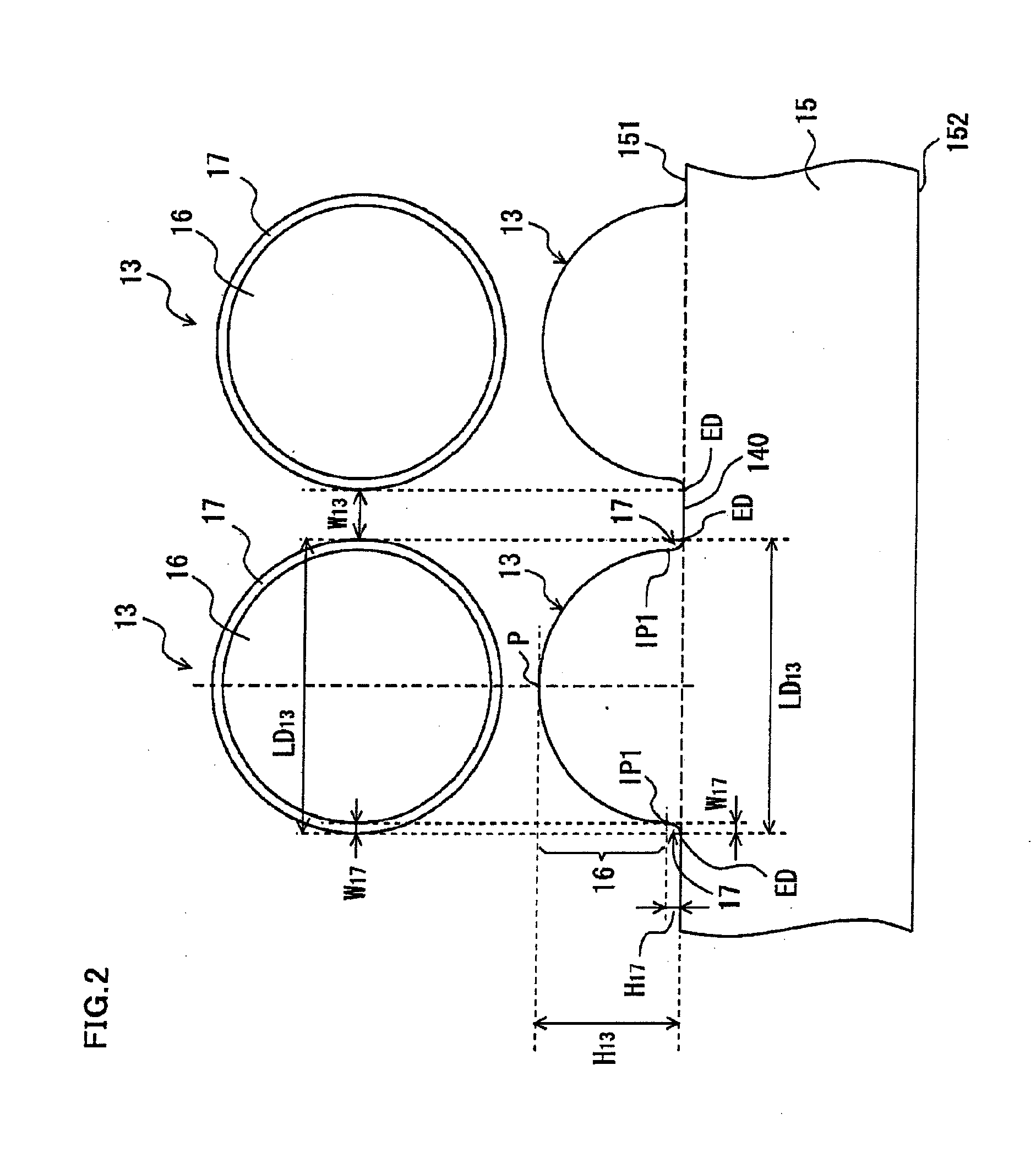
[0027]Referring to FIGS. 1 and 2, a micro lens array sheet 14 has a sheet type substrate 15 and micro lenses 13 provided in a lattice arrangement on one surface 151 of the substrate 15. Note that the other surface 152 on the opposite side to the surface 151 is flat.

[0028]The surface of the micro lens 13 includes a convex part 16 and a peripheral edge part 17. The convex part 16 is the part from the peak P to the peripheral edge part 17 of the micro lens 13 and has a spherical surface. The peripheral edge part 17 is formed between the convex part 16 and the substrate 15. The peripheral edge part 17 is curved in a concave shape and smoothly connected to the surface 151. As shown in FIG. 2, the surface of the micro lens 1...


PUM

PropertyMeasurementUnit
Fractionaaaaaaaaaa
Lengthaaaaaaaaaa
Lengthaaaaaaaaaa

Abstract

A micro lens array sheet includes a sheet type base and a plurality of micro lenses arranged on the base. The surface of each micro lens includes a convex part and a peripheral edge part. The convex part has a spherical or elliptical surface. The peripheral edge part is formed between the convex part and the base and curved in a concave shape. Since the surface of the peripheral edge part is curved in a concave shape, the flat part can be narrower than a conventional micro lens array sheet. Therefore, luminance unevenness attributable to the flat part can be suppressed.

Description

TECHNICAL FIELD[0001]The present invention relates to a micro lens array sheet and a molding roll and more specifically to a micro lens array sheet for use in a backlight device and a molding roll for manufacturing the micro lens array sheet.BACKGROUND ART[0002]A display device such as a liquid crystal display needs high front side luminance. Therefore, a backlight device included in such a display device has an optical lens sheet laid thereon in order to improve the front side luminance.[0003]A micro lens array sheet is an optical lens sheet used in a backlight device to improve the front side luminance. Such micro lens array sheets each for use in a backlight device are disclosed by JP 2004-145329 A, JP 2004-145328 A, JP 2004-126376 A, JP 2004-191611 A, and JP 2004-309557 A.[0004]The micro lens array sheet is sheet-shaped and has a plurality of convex lenses (micro lenses) in a lattice arrangement on one surface. The micro lens array sheet for use in a backlight device improves th...

Claims


Application Information

Patent Timeline
IPC IPC(8): G02B27/12B29D11/00
CPCG02B3/0025G02B3/0031G02F2001/133607G02F1/133606G02B3/0056G02F1/133607G02F1/1335G02B5/02G02B3/00
Inventor KODERA, YUJIYAMADA, YUKINORIISHIHARA, NOBUYASUHAYASHIHARA, SHIROU
Owner MAXELL HLDG LTD
Why Eureka
Try Eureka