Thin-film capacitor

a thin-film capacitor and capacitor technology, applied in the field of thin-film capacitors, to achieve the effect of less rigidity, and warpage of thin-film capacitors to be restrained

Inactive Publication Date: 2009-10-01
TDK CORPARATION
View PDF8 Cites 33 Cited by
  • Summary
  • Abstract
  • Description
  • Claims
  • Application Information

AI Technical Summary

Benefits of technology

[0008]When convex portions are arranged in the divisions, the locations of the ends of the convex portions are staggered, not aligned, in the direction orthogonal to the predetermined direction. In other words, in a projection of a division from the direction orthogonal to the predetermined direction, no parts other than the above division will remain in the projected image. When the locations of the ends of the convex portions are staggered in this manner, the trenches are formed along crooked lines between the convex portions. As the trench parts are relatively less rigid than the protrusion parts, when linearly linked trenches are formed, the lower thin-film capacitor rigidity in the direction orthogonal to the trenches in those parts will tend to result in warpage. However, the trenches are crooked, as noted above, so that there are fewer parts in which trenches are linearly formed, thus allowing warpage of the thin-film capacitor to be restrained. There are also fewer parts in which trenches are linearly formed when convex portions are arranged in parts other than the above divisions, thus similarly allowing warpage of the thin-film capacitor to be restrained.
[0009]The divisions having the extending parts will preferably include a division having a shape in which two or more strips orthogonal to each other are joined. This will allow warpage to be restrained even more effectively. When convex portions are formed in these divisions, the convex portions themselves will also be stably formed, and the convex portions will therefore sustain less damage during the step of forming convex portions or subsequent steps. This will allow thin-film capacitors to be produced with higher yields. Another advantage is that a high-density electrode surface area can be formed.
[0010]In the thin-film capacitor pertaining to the present invention, at least one protrusion is preferably arranged on any line within the main plane of the substrate. When only trenches are continuously formed on lines in the main plane of the substrate, the effect in restraining warpage in the direction orthogonal to the lines will be lower.
[0011]The thin-film capacitor of the present invention will allow the electrode surface area to be increased in order to achieve a high capacitance while adequately restraining warpage. Arranging convex portions or trenches in parts where divisions end in a predetermined direction will alleviate stress in that direction more than when convex portions or trenches are formed over the entire area in the predetermined direction. Alleviating stress will restrain current leakage caused by damage or the like to the dielectric film.

Problems solved by technology

As the trench parts are relatively less rigid than the protrusion parts, when linearly linked trenches are formed, the lower thin-film capacitor rigidity in the direction orthogonal to the trenches in those parts will tend to result in warpage.

Method used


Image

  • Thin-film capacitor
  • Thin-film capacitor
  • Thin-film capacitor

Examples


Embodiment Construction

[0030]Preferred embodiments of the present invention will be described in detail below with reference to the attached drawings as needed. However, the invention is not limited to the following embodiments. In the figures, identical or corresponding elements will be indicated by the same symbol. Elements that have already been described will not be described again where appropriate.

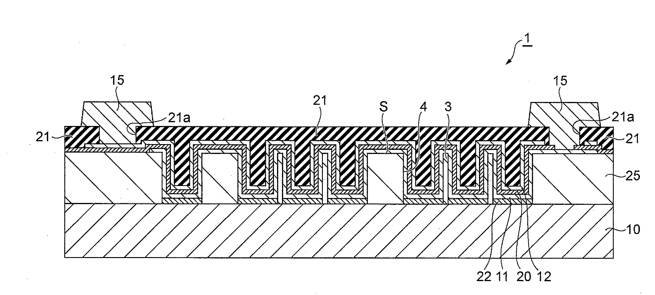
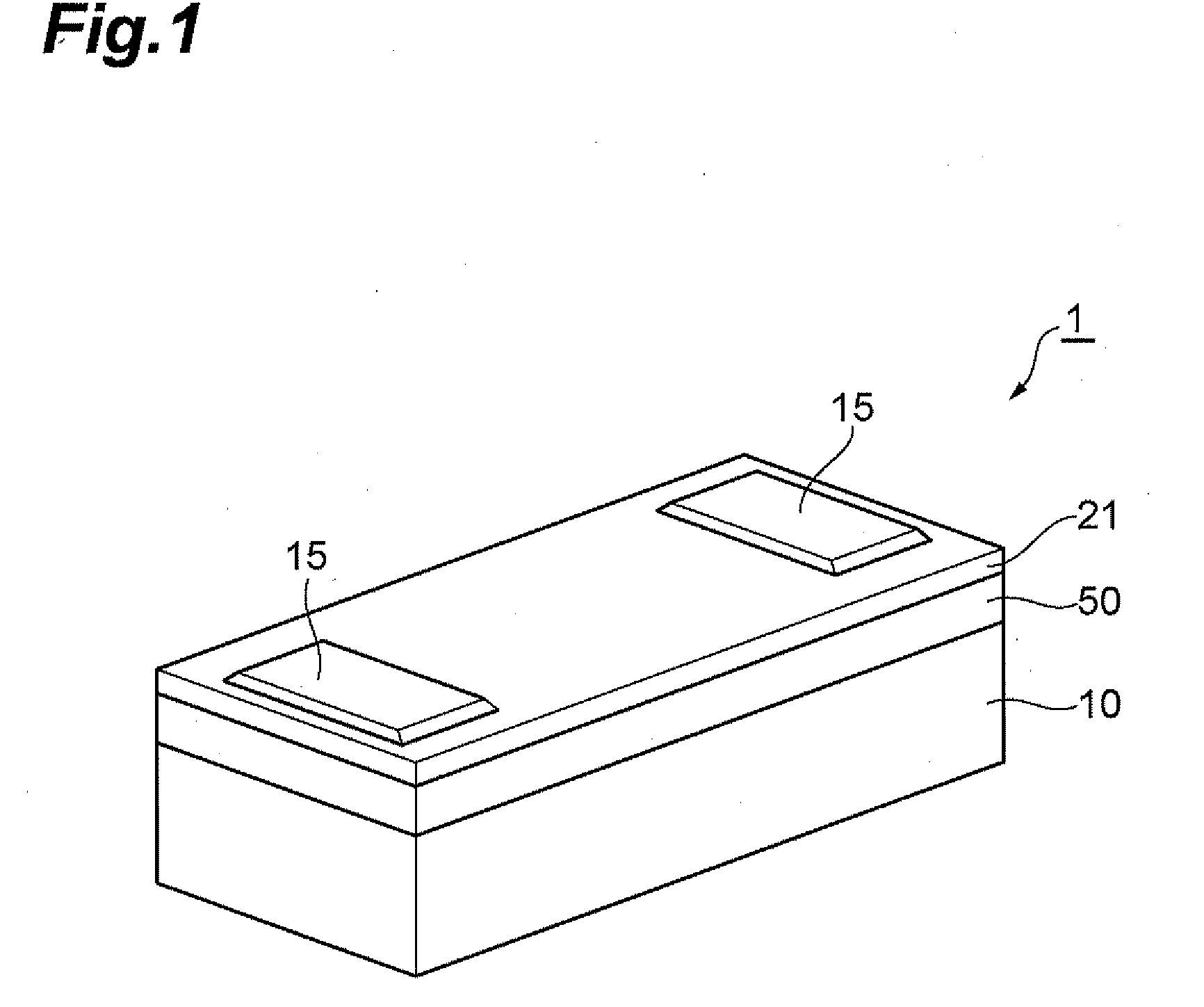
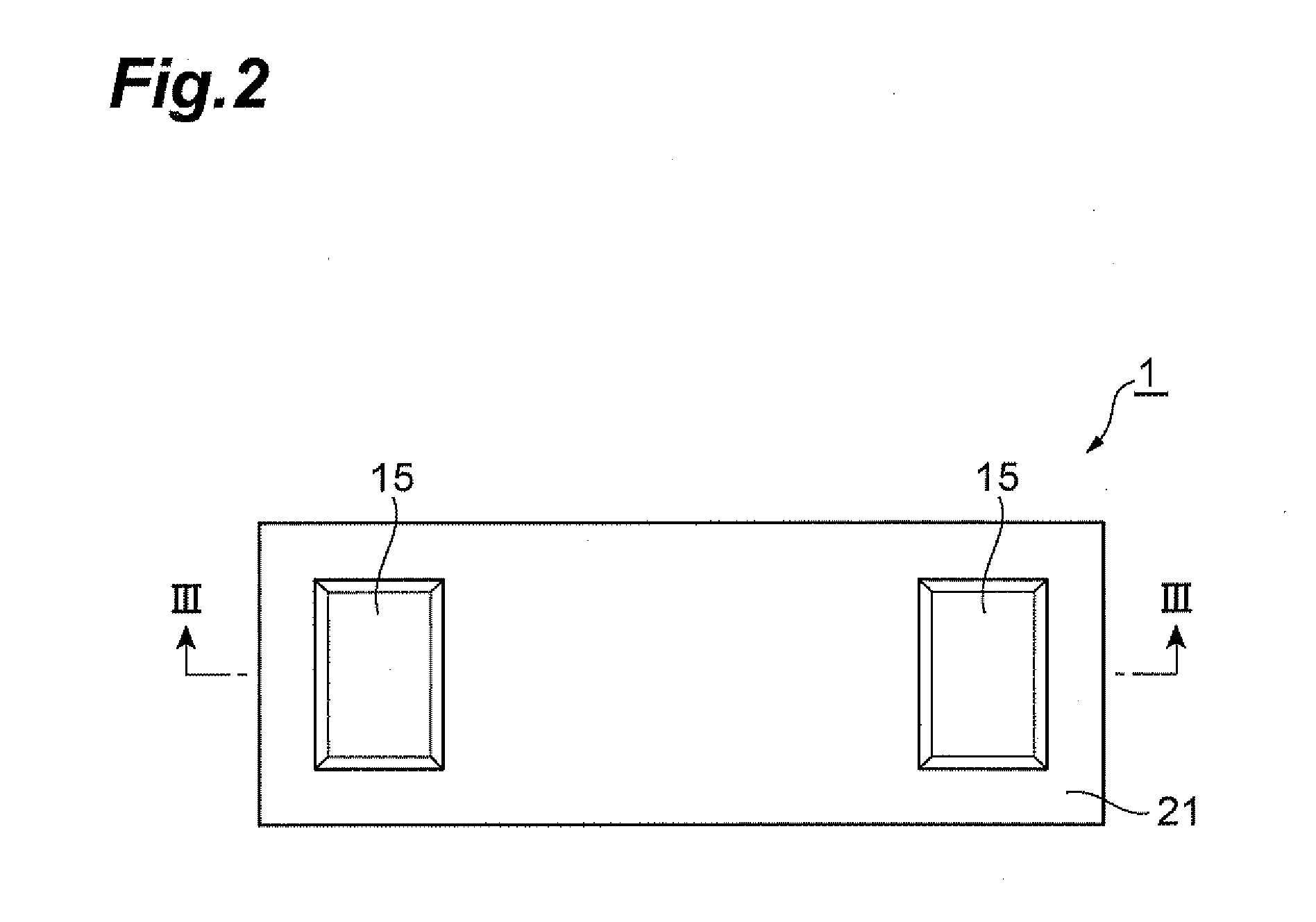
[0031]FIGS. 1 and 2 are a perspective view and plan view, respectively, showing an embodiment of a thin-film capacitor. FIG. 3 is an end view along line III-III in FIG. 2. The thin-film capacitor 1 shown in FIGS. 1 through 3 includes a substrate 10, a dielectric film 20 provided on one side of the substrate 10, a bottom electrode 11 and top electrode 12 provided on either side of the dielectric film 20, a protective film 21 that is provided on the top electrode 12 on the other side of the dielectric film 20 from the substrate 10 and that has two openings 21a formed therein through which a portion of the bo...


PUM


Abstract

An object of the present invention is to restrain warpage in a thin-film trench capacitor. A thin-film capacitor includes a substrate, a dielectric film, and a pair of electrodes, and the dielectric film is provided along a concave-convex surface on which are formed a plurality of convex portions extending away from the substrate. The concave-convex surface forms a pattern having one or more divisions arranged in a plane parallel to the main plane of the substrate, and the convex portions are arranged in either parts of the divisions or other parts. At least some of the divisions have parts extending along the x axial direction, and two or more of the extending parts overlap each other and terminate at locations that are different from each other, as viewed from the y axial direction orthogonal to the x axial direction.

Description

BACKGROUND OF THE INVENTION[0001]1. Field of the Invention[0002]The present invention relates to a thin-film capacitor.[0003]2. Related Background Art[0004]What are referred to as thin-film trench capacitors are conventionally known, wherein the electrode surface area is expanded by forming trenches in the substrate in order to make smaller, higher capacity thin-film capacitors (Japanese Patent Application Laid-Open No. 06-325970).[0005]However, a problem with conventional thin-film trench capacitors is that they tend to warp when exposed to external heat. The problem of warping tends to become more obvious particularly when attempts are made to increase the trenches in order to achieve a high capacitance. Capacitor warpage results in various drawbacks such as variability in the properties of dielectric films, and there is thus strong demand to adequately restrain such warpage.SUMMARY OF THE INVENTION[0006]An object of the present invention is therefore to restrain warpage in thin-f...

Claims


Application Information

Patent Timeline
Patent Type & Authority Applications(United States)
IPC IPC(8): H01G4/06
CPCH01G4/33H01G4/06
Inventor OHTSUKA, TAKASHIOKUZAWA, NOBUYUKI
Owner TDK CORPARATION
Why Eureka
Try Eureka