
Lens assembly and imaging apparatus

Inactive Publication Date: 2009-10-01
FUJI PHOTO OPTICAL CO LTD
View PDF6 Cites 12 Cited by
  • Summary
  • Abstract
  • Description
  • Claims
  • Application Information

AI Technical Summary

Benefits of technology

[0013]In view of the above circumstances, the invention provides a lens assembly that is improved in waterproof performance and an imaging apparatus.
[0015]In this lens assembly, as the second screw formed on the inner wall surface of the lens holder is screwed into the first screw formed on the outer peripheral surface of the lens frame, the lens frame is deformed in such the direction as to press the O-ring. Thereby, the O-ring is sufficiently pressed. Thus, even if a mounting strength between the lens and the lens frame, which press the O-ring, is lowered in the assembling process, the O-ring is sufficiently pressed by the lens frame which is deformed by screwing the lens holder. Accordingly, it is possible to assemble the lens assembly improved in waterproof performance. Furthermore, in the case where the assembled lens assembly is mounted on an on-board camera, even if dimensions of the lens and the lens frame are varied with time, due to change of environmental conditions such as humidity and temperature, or the like, the O-ring is sufficiently pressed by the lens frame which is deformed by screwing the lens holder into. Thus, it is possible to maintain excellent waterproof performance.
[0021]Since the above imaging apparatus includes the above-mentioned lens assembly, the imaging apparatus is improved in waterproof performance.
[0022]With the above configurations, it is possible to provide a lens assembly and an imaging apparatus improved in waterproof performance.

Problems solved by technology

Here, if variation occurs in mounting strength between the taking lens and the lens frame in the assembling process of the lens assembly, a problem arises in that variation occurs in waterproof performance.
Furthermore, when the lens assembly is mounted on an on-board camera, if dimensions of the taking lens and the lens frame are varied with time, due to change of environmental conditions such as humidity and temperature, or the like, sometimes the mounting strength between the taking lens and the lens frame may deteriorate.
In such a case, a problem arises in that waterproof performance deteriorates.
Accordingly, the related-art lens assembly has a problem of low waterproof performance.

Method used


Image

  • Lens assembly and imaging apparatus
  • Lens assembly and imaging apparatus
  • Lens assembly and imaging apparatus

Examples


first embodiment

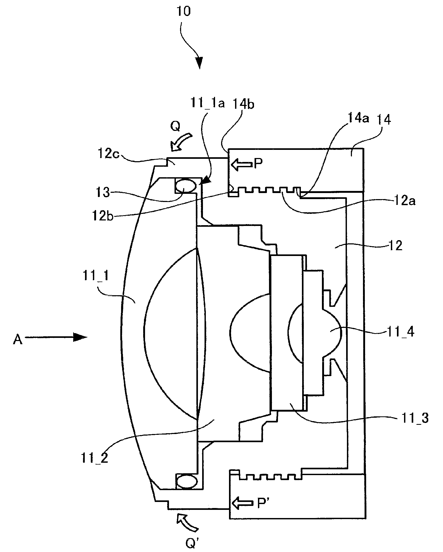
[0029]FIG. 1 is a view illustrating a section of a lens assembly according to the invention, taken along an optical axis of a taking lens.

[0030]A lens assembly 10 according to the first embodiment shown in FIG. 1 includes a taking lens 11_1 of a first group, a taking lens 11_2 of a second group, a taking lens 11_3 of a third group, and a taking lens 11_4 of a fourth group in order from an incident-side of subject light A. On the periphery of the taking lens 11_1, a groove 11_1a is provided.

[0031]Furthermore, the lens assembly 10 includes a lens frame 12 for housing the taking lenses 11_1, 11_2, 11_3, and 11_4. In the lens frame 12, a male screw 12a (which corresponds to an example of a first screw) is formed on the outer peripheral surface thereof.

[0032]Furthermore, the lens assembly 10 includes an O-ring 13 disposed between the periphery of the taking lens 11_1 and the inner surface of the lens frame 12. Specifically, the O-ring 13 is fitted into the groove 11_1a, which is provided...

second embodiment

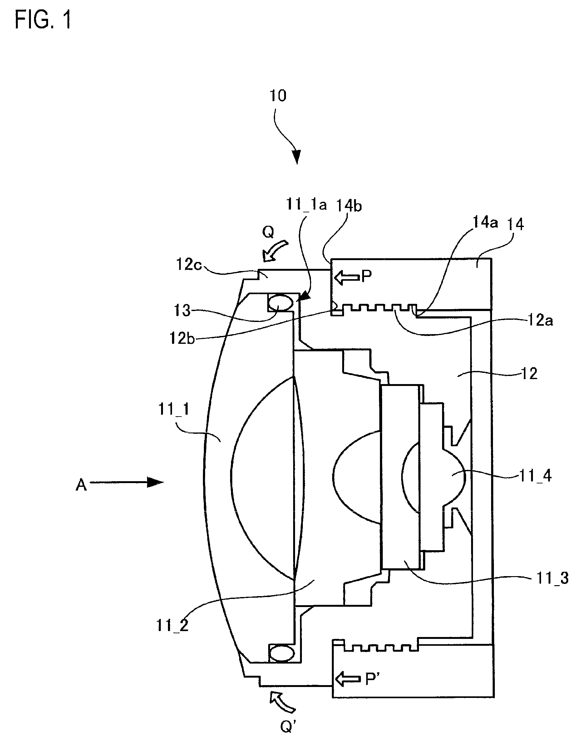
[0038]FIG. 2 is a view illustrating a section of a lens assembly according to the invention, taken along an optical axis of a taking lens.

[0039]A lens assembly 20 according to the second embodiment shown in FIG. 2 includes a taking lens 21_1 of a first group, a taking lens 21_2 of a second group, a taking lens 21_3 of a third group, and a taking lens 21_4 of a fourth group in order from the incident side of subject light A. On the periphery of the taking lens 21_1, a groove 21_1a is provided.

[0040]Furthermore, the lens assembly 20 includes a lens frame 22 for housing the taking lenses 21_1, 21_2, 21_3, and 21_4. Specifically, a male screw 22a (which corresponds to another example of the first screw) is formed on the outer peripheral surface of the lens frame 22 and in an area that is overlapped, in the direction orthogonal to the optical axis of the taking lenses 21_1, 21_2, 21_3, and 21_4, with a position where an O-ring 23 is disposed.

[0041]Furthermore, the lens assembly 20 includ...

third embodiment

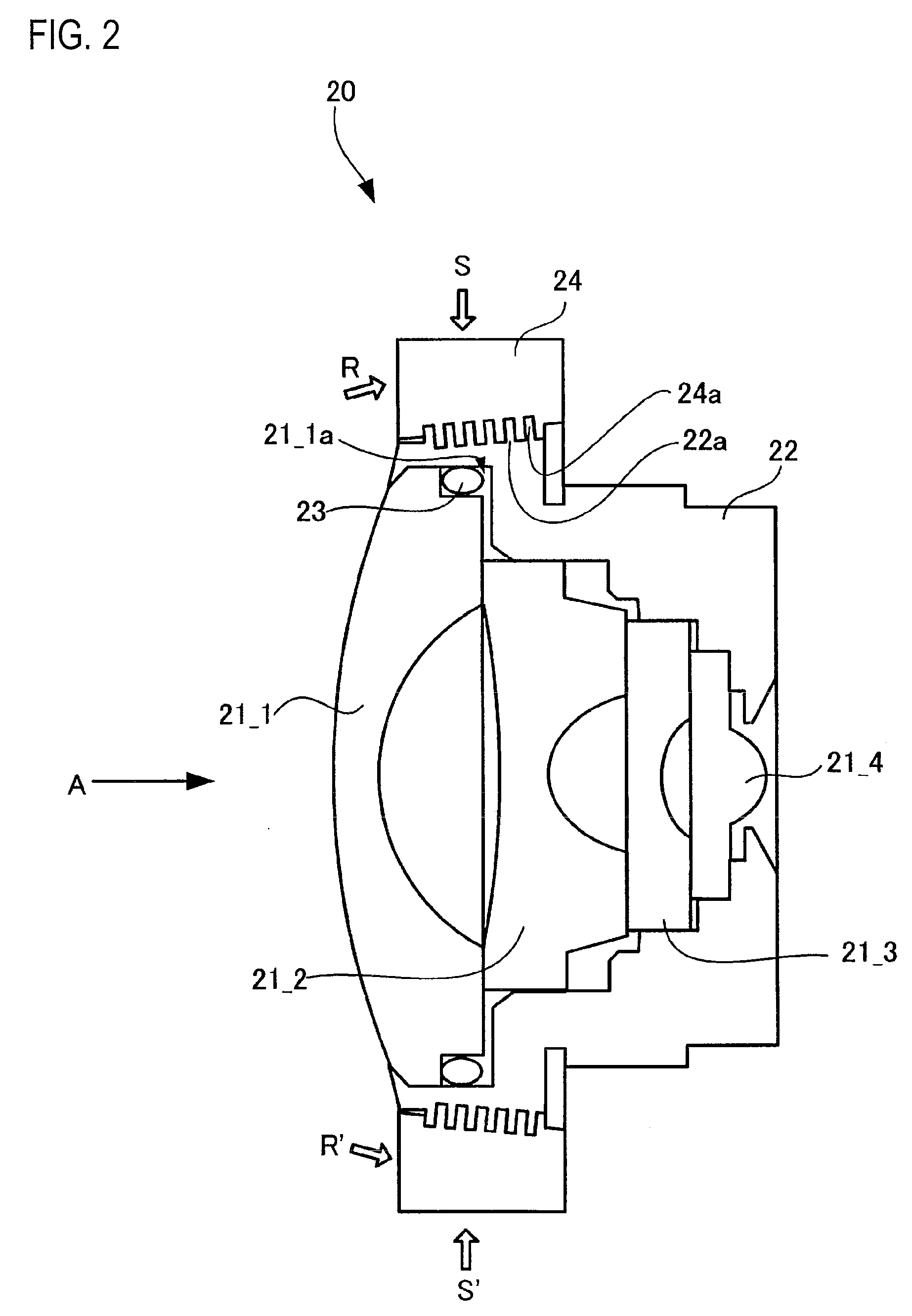
[0046]FIG. 3 is a view illustrating a section of a lens assembly according to the invention, taken along an optical axis of a taking lens.

[0047]Furthermore, in the following description, elements the same as those of the lens assembly 20 shown in FIG. 2 will be referenced by the same reference numerals and signs. Differences between the third embodiment and the second embodiment will be described below.

[0048]As compared with the lens assembly 20 shown in FIG. 2, the lens assembly 30 according to the third embodiment shown in FIG. 3 is different in that the lens holder 24 is replaced with a lens holder 34.

[0049]As shown in FIG. 3, the lens holder 34 is a member formed so that its thickness is larger on the right side than on the left side. In the lens holder 34, a female screw 34a (which corresponds to another example of the second screw described) has a second taper shape and is adapted to be screwed with the male screw 22a from a side opposite to the incidence side of the subject l...


PUM


Abstract

Taking lenses 11—4, 11—3, and 11—2 are housed in a lens frame 12. Then, the O-ring 13 is fitted into a groove 11—1a provided on the periphery of the taking lens 11—1, and the taking lens 11—1 is housed in the lens frame 12. Subsequently, an anterior surface 14b of a lens holder 14 in a screwing direction (directions of arrows P and P′) comes into contact with a wall surface 12b of the lens frame 12. Then, the lens holder 14 is gradually screwed into the lens frame 12. Thereby, a deformable portion 12c of the lens frame 12 on an O-ring 13 side of the wall surface 12b is deformed in such a direction (directions of arrows Q and Q′) as to press the O-ring 13.

Description

CROSS-REFERENCE TO RELATED APPLICATIONS[0001]This application is based upon and claims the benefit of priority from the Japanese Patent Application No. 2008-88517 filed on Mar. 28, 2008; the entire contents of which are incorporated herein by reference.BACKGROUND OF THE INVENTION[0002]1. Technical Field[0003]The invention relates to a lens assembly equipped with a lens for forming an image using subject light on an imaging device and to an imaging apparatus having the lens assembly.[0004]2. Description of the Related Art[0005]Recently, cameras become mounted in vehicles. Cameras provided in vehicles are used as surveillance cameras or as driving-assistance cameras. Since display screens have been provided on driver's seats as navigation systems have become popular, the latter case is intended to display an image taken by the camera on the display screen.[0006]In such on-board cameras, most of those are required to have waterproof performance since those are mainly used outside of ve...

Claims


Application Information

Patent Timeline
IPC IPC(8): G03B17/08
CPCG02B7/021G03B17/08G02B7/026
Inventor SASAKI, NAOKI
Owner FUJI PHOTO OPTICAL CO LTD
Features
  • Generate Ideas
  • Intellectual Property
  • Life Sciences
  • Materials
  • Tech Scout
  • Unparalleled Data Quality
  • Higher Quality Content
  • 60% Fewer Hallucinations
Learn More