

Multi-cylinder engine
a multi-cylinder engine and engine technology, applied in the direction of electric control, process and machine control, instruments, etc., can solve the problems of increasing increasing the number of operating cylinders, and increasing so as to reduce the internal pressure of the cylinder, reduce the effect of vibration and noise effectively suppressed, and reduce the frequency of vibration and noise generated during the selected cylinder operation
- Summary
- Abstract
- Description
- Claims
- Application Information
AI Technical Summary
Benefits of technology
Problems solved by technology
Method used
Image

Examples
example 1
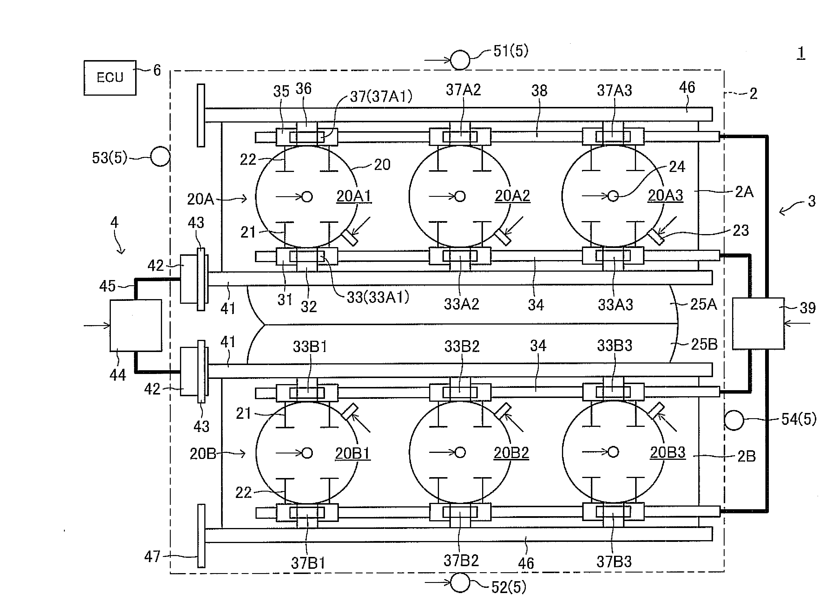
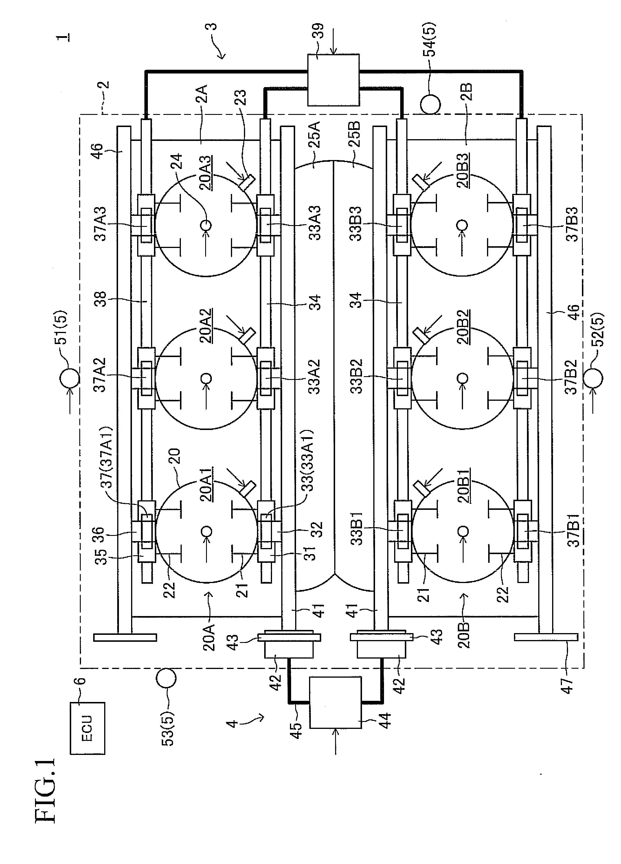
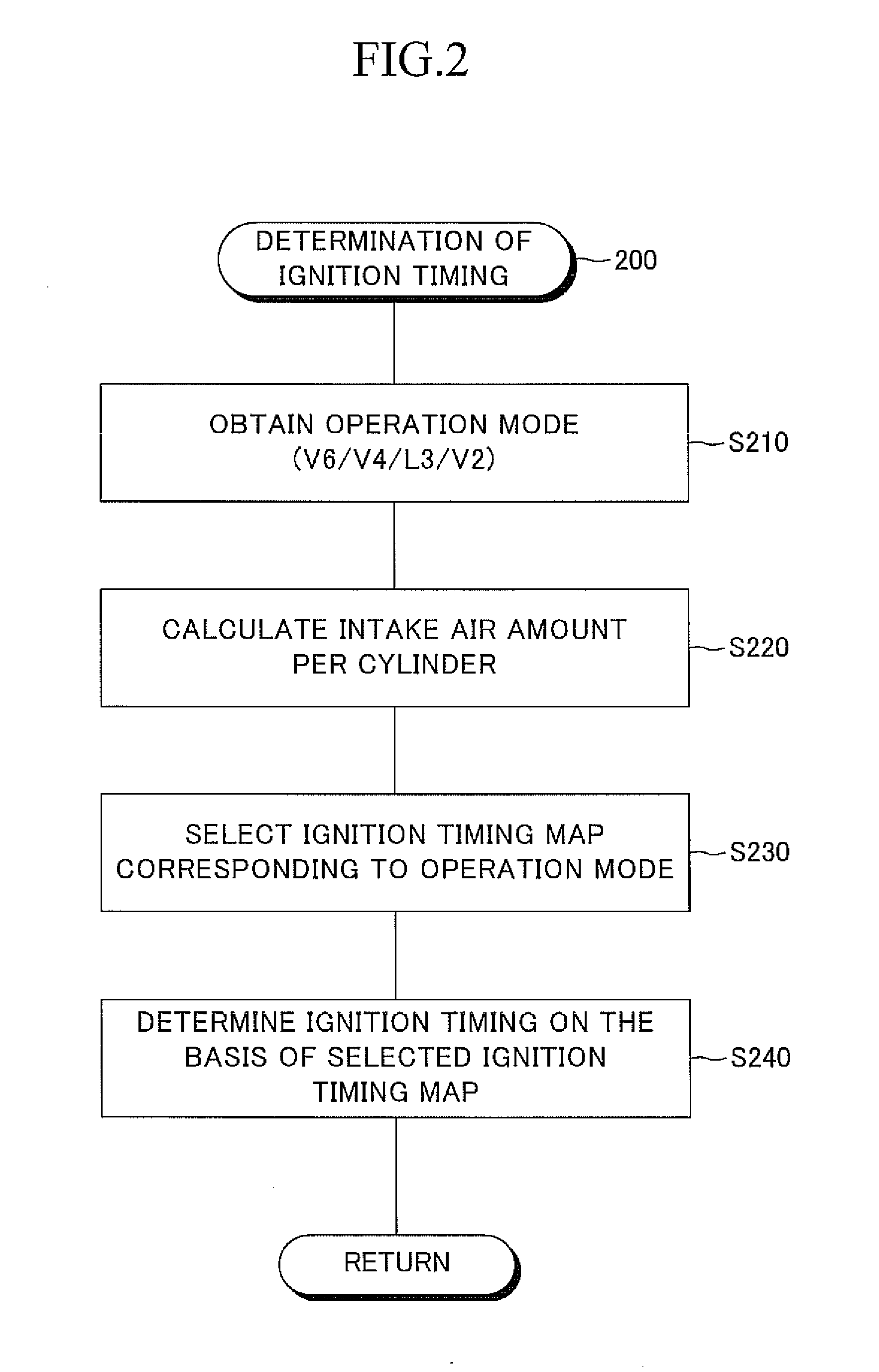
[0061]FIG. 2 is a flowchart showing a specific example of an ignition timing determination routine 200 executed by the ECU 6 shown in FIG. 1. The ECU 6 repeatedly executes this routine 200 every time the crank angle reaches a predetermined value (e.g., BTDC90° CA).
[0062]When this routine is executed, an operation mode at the present, which is determined on the basis of the operating conditions, etc. through execution of a predetermined operation mode determination routine, is acquired in S210. Next, in S220, an intake air amount per cylinder is calculated on the basis of an intake air flow rate Ga which is determined from an output of an air flow meter, the above-mentioned operation mode, etc.
[0063]Subsequently, in S230, an ignition timing map corresponding to the operation mode is selected. This ignition timing map is a two-dimensional map for determining ignition timing on the basis of engine speed and intake air amount per cylinder (load factor), and is prepared for each operatio...
example 2
[0067]In the present specific example (second specific example), the same flowchart as employed in the first specific example is used.
[0068]However, unlike the first specific example, in the present specific example, the ignition timing maps for the above-mentioned operation modes are formed such that, when the ignition timings determined by use of the ignition timing maps are compared under the same engine speed and load factor, the ignition timing is retarded only in the four-cylinder operation mode in which explosion occurs at irregular intervals (for example, when the speed is 2000 rpm and the load factor is 40%, the ignition timing [BTDC° CA] is set in such a manner that the ignition timing is 30° in the full-cylinder operation mode, 25° in the four-cylinder operation mode, 30° in the three-cylinder operation mode, and 30° in the two-cylinder operation mode).
example 3
[0069]In the present specific example (third specific example), the same flowchart as employed in the first specific example is used.
[0070]However, unlike the first specific example, in the present specific example, the ignition timing maps for the above-mentioned operation modes are formed such that, when the ignition timings determined by use of the ignition timing maps are compared under the same engine speed and load factor, the ignition timing is retarded by the greatest amount in the four-cylinder operation mode in which explosion occurs at irregular intervals, and the amount of the ignition timing retard increases as the number of operating cylinders decreases in the remaining operation modes in which explosion occurs at constant intervals (for example, when the speed is 2000 rpm and the load factor is 40%, the ignition timing [BTDC° CA] is set in such a manner that the ignition timing is 30° in the full-cylinder operation mode, 23° in the four-cylinder operation mode, 27° in...
PUM
 Abstract
Description
Claims
Application Information