

Linear Actuator
a technology of actuators and actuators, applied in the direction of machine supports, other domestic objects, etc., can solve the problems of internal damage and inner damage, and achieve the effect of moving stably
- Summary
- Abstract
- Description
- Claims
- Application Information
AI Technical Summary
Benefits of technology
Problems solved by technology
Method used
Image

Examples
Embodiment Construction
[0025]The present invention will be clearer from the following description when viewed together with the accompanying drawings, which show, for purpose of illustrations only, the preferred embodiment in accordance with the present invention.
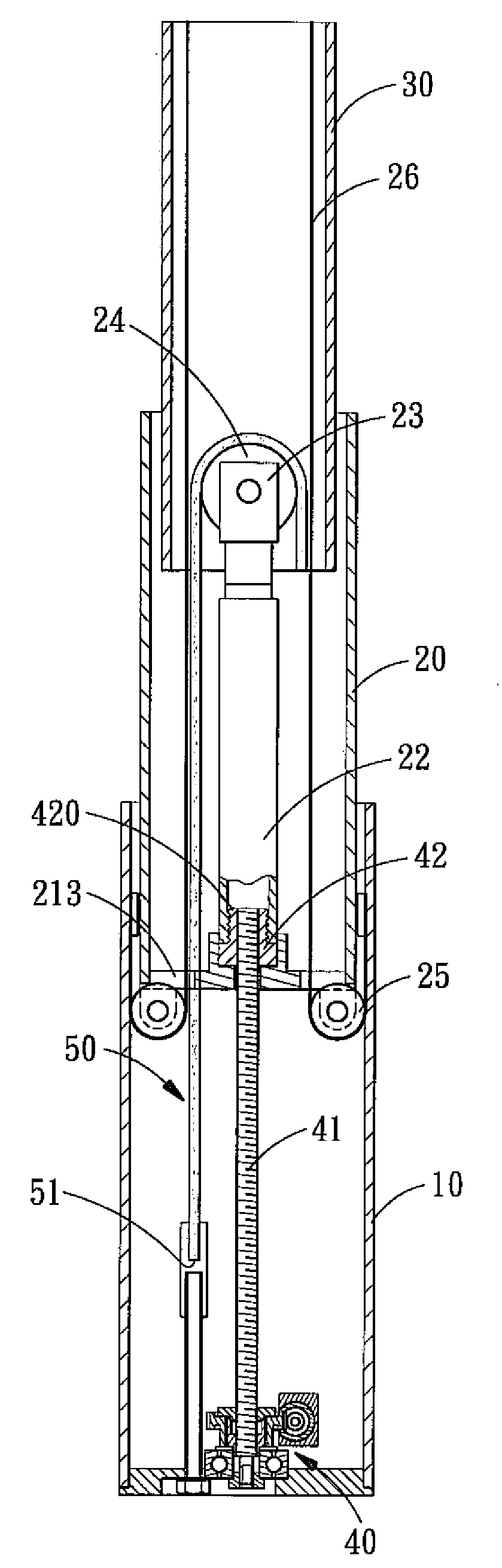
[0026]Referring to FIGS. 5-7, a linear actuator in accordance with the present invention comprises a polygonal outer tube 10 which is provided for the insertion of an intermediate tube 20 and an inner tube 30 that are shaped the same as the outer tube 10. The polygonal configuration allows the outer tube 10, the intermediate tube 20 and the inner tube 30 to extend and retract with respect to one other in the axial direction without moving relative to one another in the radial direction (providing a restriction function in the radial direction), thus keeping the stability of the extending / retracting movement. The respective tubes 10, 20, 30 may be in the form of a triangle, quadrangle or pentagon in cross section. The outer tube 10 is disposed at ...
PUM
 Abstract
Description
Claims
Application Information