Monitoring systems and methods for sewer and other conduit systems

a monitoring system and conduit technology, applied in the direction of fluid tightness measurement, instrumentation, service pipe system, etc., can solve the problems of untreated wastewater spillage, untreated wastewater spillage out of manholes, untreated wastewater spillage into public and private property,

Active Publication Date: 2009-10-08
JUNIVERSITI OF NORT KAROLINA EHT SHARLOTT
View PDF11 Cites 51 Cited by
  • Summary
  • Abstract
  • Description
  • Claims
  • Application Information

AI Technical Summary

Benefits of technology

[0004]In various exemplary embodiments, the present invention provides monitoring systems and methods for sewer and other conduit systems. These monitoring systems and methods allow wastewater utilities and the like to implement dynamic predictive maintenance systems (DPMSs) and institute just-in-time maintenance programs for mitigating combined sewer overflows (CSOs), involving both wastewater and storm water, and SSOs, involving only wastewater. For example, the monitoring systems and methods allow for the detection of blockages in low flow pipes due to grease clogs, root balls, and the like, as well as breakages. Maintenance efforts may then be directed to areas where problems are the most likely, as well as where they already exist. It will be readily apparent to those of ordinary skill in the art, that although many of the examples provided herein involve sewer systems, the monitoring systems and methods of the present invention are applicable to any conduit systems, such as oil delivery systems, other fluid delivery systems, gas delivery systems, etc.—i.e. any systems that include a network of “pipes” for delivering one or more “materials” (these terms being given their broadest possible interpretations).
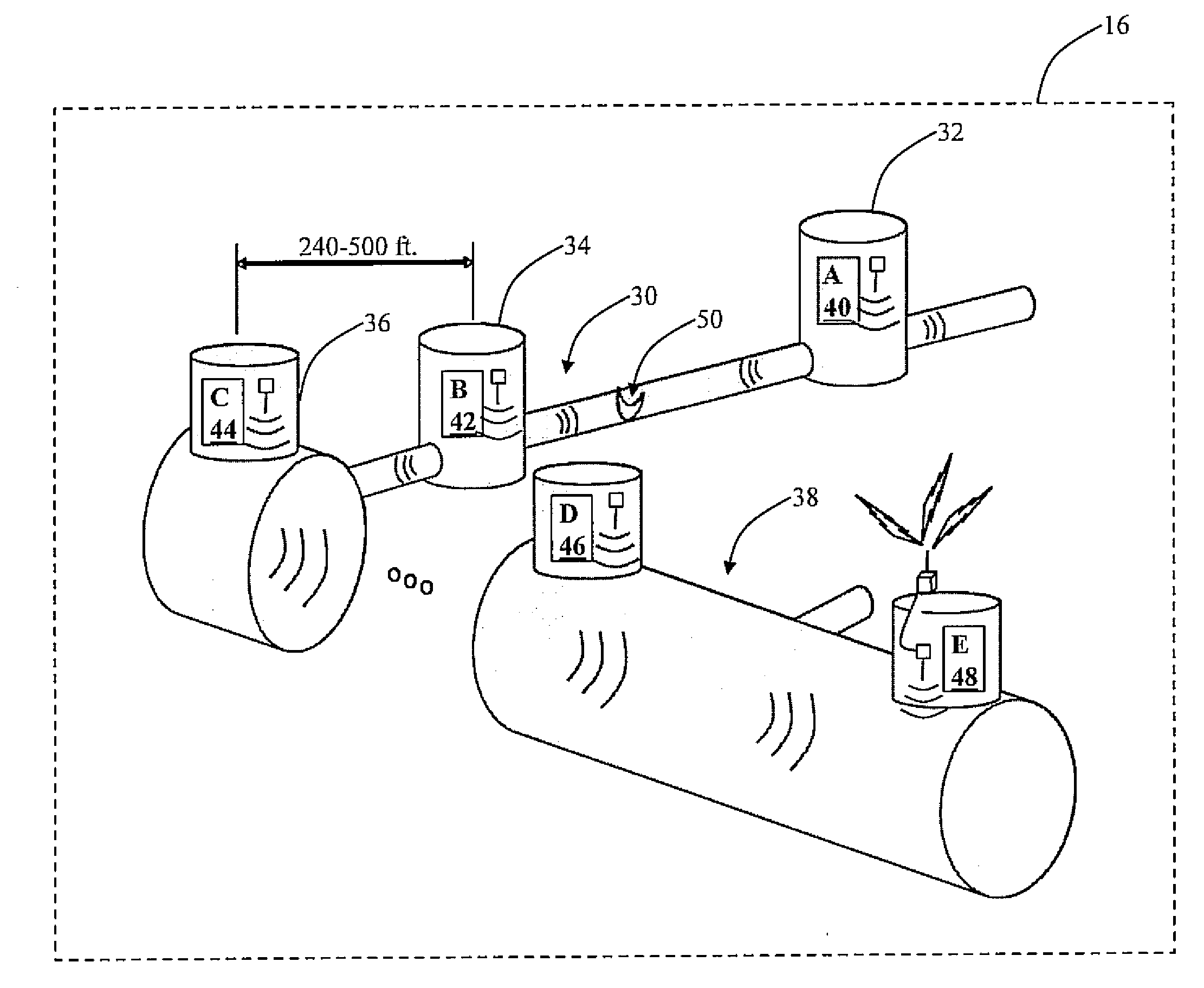
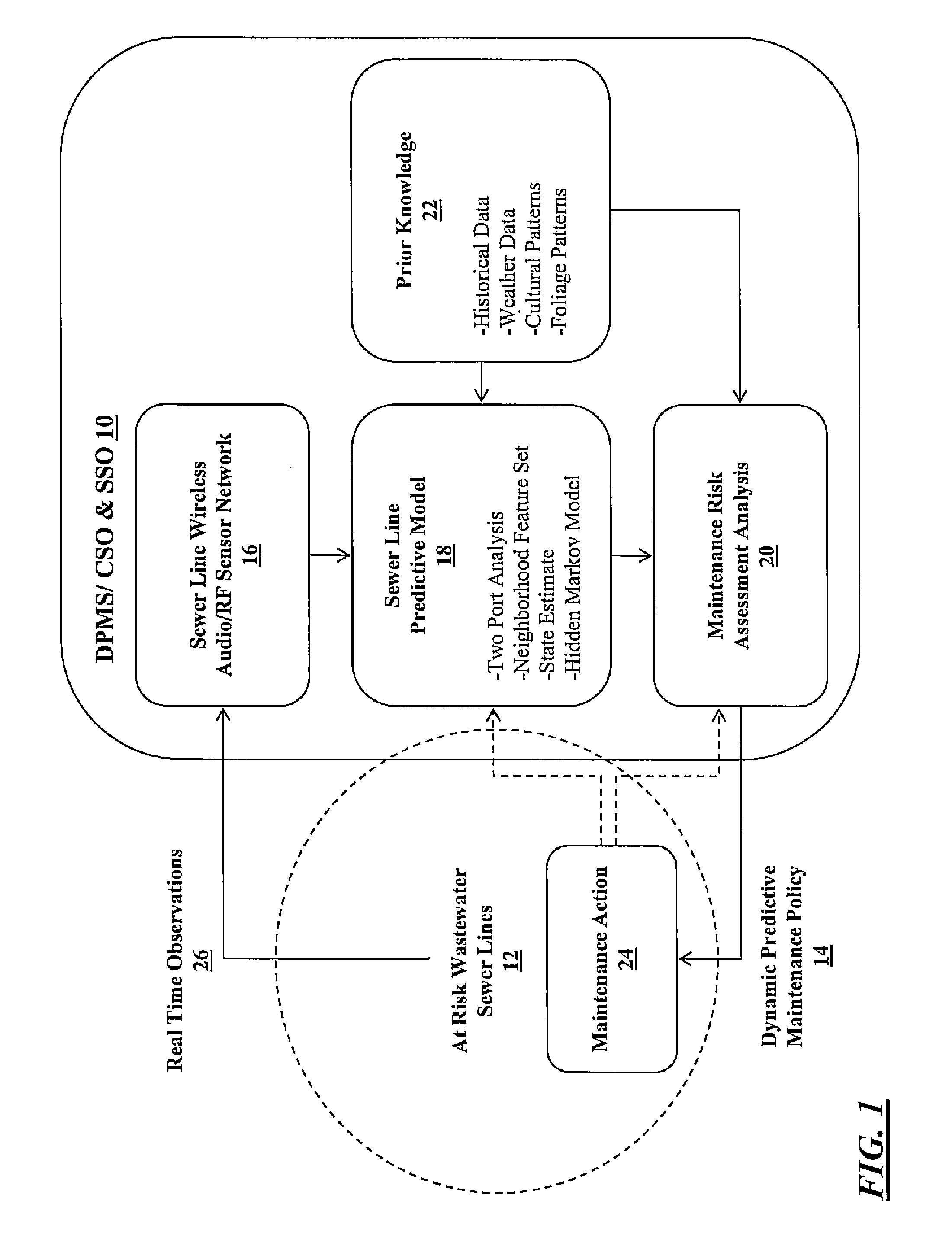
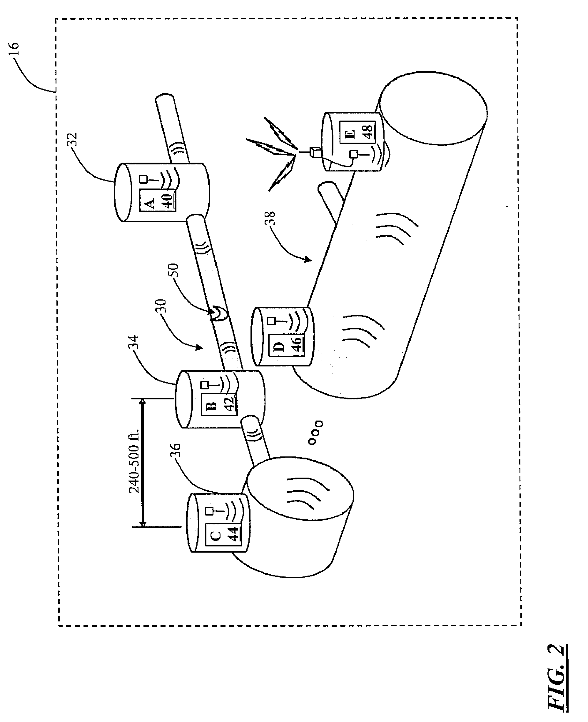
[0005]In one exemplary embodiment, the present invention provides a monitoring system for a conduit network including one or more conduit sections joined at one or more conduit nodes, including: one or more sensor devices disposed at selected ones of the one or more conduit nodes, wherein each of the one or more sensor devices is operable for sensing a blockage or breakage in an associated conduit section, and wherein each of the one or more sensor devices is operable for communicating blockage or breakage information to a central location. Preferably, each of the sensor devices includes one of an audio sensor device and a radio frequency sensor device and communicates via this medium. Each of the sensor devices is operable for sensing the blockage or breakage in the associated conduit section by measuring an attribute of a transmitted / received signal, alone or in combination with another sensor device. Each of the sensor devices is operable for communicating the blockage or breakage information to the central location via a wireless link. The monitoring system also includes a conduit network predictive model provided at the central location and operable for processing the blockage or breakage information to form a dynamic predictive maintenance policy that dictates a maintenance action. The monitoring system further includes a historical database that informs the conduit network predictive model. The monitoring system still further includes an alarm mechanism that is triggered at the central location by the blockage or breakage information if a predetermined blockage or breakage threshold is crossed. Optionally, the conduit network includes a sewer line network, the conduit sections include sewer line sections, and the conduit nodes include manholes.
[0006]In another exemplary embodiment, the present invention provides a monitoring method for a conduit network including one or more conduit sections joined at one or more conduit nodes, including: disposing one or more sensor devices at selected ones of the one or more conduit nodes, wherein each of the one or more sensor devices is operable for sensing a blockage or breakage in an associated conduit section, and wherein each of the one or more sensor devices is operable for communicating blockage or breakage information to a central location. Preferably, each of the sensor devices includes one of an audio sensor device and a radio frequency sensor device and communicates via this medium. Each of the sensor devices is operable for sensing the blockage or breakage in the associated conduit section by measuring an attribute of a transmitted / received signal, alone or in combination with another sensor device. Each of the sensor devices is operable for communicating the blockage or breakage information to the central location via a wireless link. The monitoring method also includes providing a conduit network predictive model at the central location operable for processing the blockage or breakage information to form a dynamic predictive maintenance policy that dictates a maintenance action. The monitoring method further includes providing a historical database that informs the conduit network predictive model. The monitoring method still further includes providing an alarm mechanism that is triggered at the central location by the blockage or breakage information if a predetermined blockage or breakage threshold is crossed. Optionally, the conduit network includes a sewer line network, the conduit sections include sewer line sections, and the conduit nodes include manholes.
[0007]In a further exemplary embodiment, the present invention provides a monitoring and maintenance method for a conduit network including one or more conduit sections joined at one or more conduit nodes, including: assessing a blockage or breakage state of each of the one or more conduit sections by measuring an attribute of an audio or radio frequency signal at each of the one or more conduit nodes; and maintaining each of the one or more conduit sections responsive to the assessed blockage or breakage state. Optionally, the blockage or breakage state is assessed at a central location. Optionally, the blockage or breakage state is assessed at the central location using a conduit network predictive model operable for processing blockage or breakage information to form a dynamic predictive maintenance policy that dictates a maintenance action. Optionally, the conduit network includes a sewer line network, the conduit sections include sewer line sections, and the conduit nodes include manholes.

Problems solved by technology

Over 34-thousand sewer overflows occur annually within the United States, resulting in the spillage of in excess of 850-billion gallons of untreated wastewater.
In Charlotte, N.C., for example, over 400 sanitary sewer overflows (SSOs) occurred in 2007 within the Charlotte-Mecklenburg Utilities (CMU) service area, resulting in the spillage of in excess of 1.6-million gallons of untreated wastewater.
Such sewer overflows are predominantly caused by blockages.
These blockages cause the untreated wastewater to spill out of manholes onto streets, into public and private property, and into waterways.
The results are property damage, environmental problems, and, in the most severe cases, public health and safety hazards.
The complexity and dynamic nature of the sewer system presents significant maintenance challenges.
Underlying maintenance policy development is an engineering tradeoff: over-maintenance results in an inefficient deployment of resources and unnecessary cost and under-maintenance results in a greater overflow risk.

Method used


Image

  • Monitoring systems and methods for sewer and other conduit systems
  • Monitoring systems and methods for sewer and other conduit systems
  • Monitoring systems and methods for sewer and other conduit systems

Examples


Embodiment Construction

[0018]Referring to FIG. 1, the DPMS 10 of the present invention utilizes real time observations of at risk wastewater sewer line sections 12 to formulate a dynamic predictive maintenance policy 14. This just-in-time dynamic predictive maintenance policy 14 minimizes the economic losses associated with conventional maintenance scheduling within at risk wastewater sewer line sections 12.

[0019]Conventional maintenance scheduling typically utilizes prior knowledge and informal risk assessment analysis to mitigate CSOs and SSOs. For example, it is known that wastewater sewer line sections that are located near restaurants and the like require regular maintenance due to improper grease handling practices.

[0020]As indicated by the random CSO and SSO distribution within many municipalities, using the current best practices in assessing at risk wastewater sewer line sections 12 is inadequate. Using historical data, weather data, cultural patterns, and foliage patterns, certain areas within a...


PUM


Abstract

The present invention provides a monitoring system for a conduit network including one or more conduit sections joined at one or more conduit nodes, including: one or more sensor devices disposed at selected ones of the one or more conduit nodes, wherein each of the one or more sensor devices is operable for sensing a blockage or breakage in an associated conduit section, and wherein each of the one or more sensor devices is operable for communicating blockage or breakage information to a central location. Optionally, each of the sensor devices includes one of an audio sensor device and a radio frequency sensor device. Each of the sensor devices is operable for sensing the blockage or breakage in the associated conduit section by measuring an attribute of a transmitted/received signal, alone or in combination with another sensor device. Each of the sensor devices is operable for communicating the blockage or breakage information to the central location via a wireless link.

Description

CROSS-REFERENCE TO RELATED APPLICATION(S)[0001]The present non-provisional patent application claims the benefit of priority of U.S. Provisional Patent Application No. 61 / 041,725, filed on Apr. 2, 2008, and entitled “SEWER SYSTEM OVERFLOW (SSO) DETECTION NETWORK,” the contents of which are incorporated in full by reference herein.FIELD OF THE INVENTION[0002]The present invention relates generally to monitoring systems and methods for sewer and other conduit systems. More specifically, the present invention relates to a network of sensors operable for predicting and detecting blockages and breakages in a sewer system, other fluid delivery system, or other gas delivery system, such that preventative and emergency maintenance may be performed with an efficient deployment of resources and major damages and losses may be prevented. This network of sensors utilizes audio and / or radio frequency (RF) signals.BACKGROUND OF THE INVENTION[0003]Over 34-thousand sewer overflows occur annually wi...

Claims


Application Information

Patent Timeline
Patent Type & Authority Applications(United States)
IPC IPC(8): E03B7/07
CPCE03F7/00Y04S20/36G01M3/243G01D2204/22Y10T137/8158Y04S20/30
Inventor HOWITT, IVAN
Owner JUNIVERSITI OF NORT KAROLINA EHT SHARLOTT
Why Eureka
Try Eureka