Methods for Detecting Fluorescent Signals in a Biological Sample

a fluorescent signal and biological sample technology, applied in the direction of fluorescence/phosphorescence, luminescent dosimeters, optical radiation measurement, etc., can solve the problems of slow process for any application, and difficulty in expressing the basis of such decision

Active Publication Date: 2009-10-08
IKONISYS INC
View PDF2 Cites 18 Cited by
  • Summary
  • Abstract
  • Description
  • Claims
  • Application Information

AI Technical Summary

Benefits of technology

[0023](a) providing an automated microscope comprising a slide stage, at least one objective lens, at least one slide cassette containing at least one mic

Problems solved by technology

Of course, such process may be slow for any application that requires a complete view of the specimen.
A number of difficulties are associated with automated microscopy.
For example, microscopists are

Method used


Image

  • Methods for Detecting Fluorescent Signals in a Biological Sample
  • Methods for Detecting Fluorescent Signals in a Biological Sample
  • Methods for Detecting Fluorescent Signals in a Biological Sample

Examples


Embodiment Construction

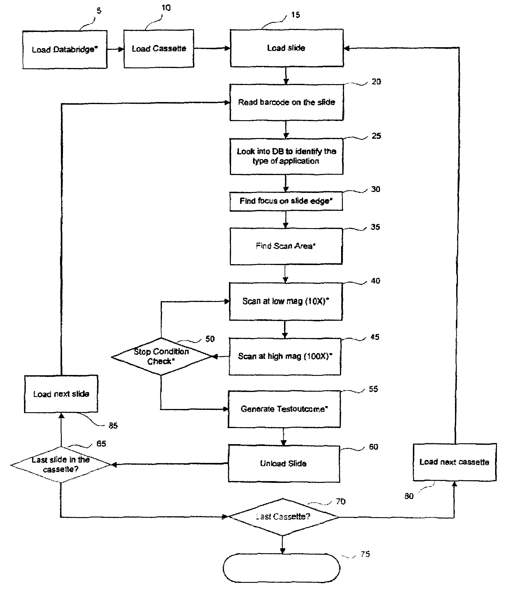
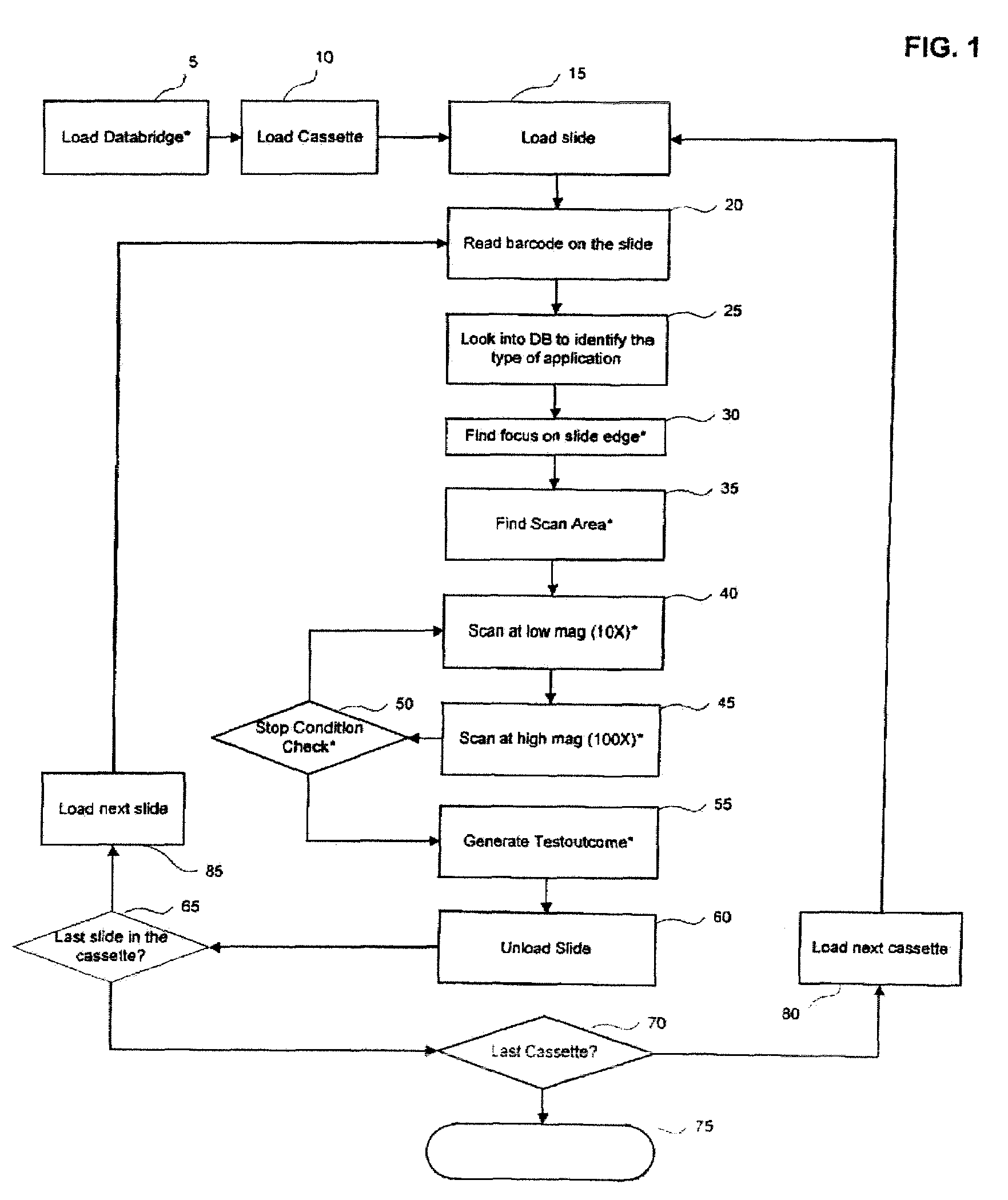
[0065]Turning to FIG. 1, there is disclosed a master diagrammatic flow chart of an embodiment of the present invention. FIG. 1 presents an overview of the various computational modules that together implement the automatic retrieval and analysis of samples on multiple slides. Such a collection of slides may arise in a research setting or in a diagnostic setting. Large numbers of slides are advantageously examined and analyzed by the automated methods disclosed herein. Biological specimens, cellular or tissue preparations, and similar subjects of investigation constitute nonlimiting examples of subjects for microscopic analysis by methods of the invention. These are generally termed “samples” or “specimens” herein. Commonly the samples include labels to assist in microscopic analysis. Frequently such labels are fluorescent labels. A sample may furthermore include more than one fluorescent labels, wherein each label has particular and distinguishable fluorescent properties, esp. disti...


PUM


Abstract

Operational means for automatic microscopic detection and analysis of fluorescent signals from a treated biological sample.

Description

CROSS-REFERENCE TO RELATED APPLICATIONS[0001]This application claims the benefit of priority of U.S. Provisional Application No. 60 / 821,557, filed Aug. 4, 2006, which is incorporated herein by reference in its entirety.BACKGROUND OF THE INVENTION[0002]All references cited in this specification, and their references, are incorporated by reference herein where appropriate for teachings of additional or alternative details, features, and / or technical background.FIELD OF THE INVENTION[0003]The present invention generally relates to the automated microscopic detection of biological structures using fluorescent tags directed to such biological structures.DESCRIPTION OF THE RELATED ART[0004]Conventional optical microscopy generally employs a microscope slide to which a biological sample has been affixed, and a single objective lens that is used to focus on discrete areas of the biological sample in a search for structures of interest, such as cells, nuclei, etc. Dimensions of the image see...

Claims


Application Information

Patent Timeline
IPC IPC(8): G01N21/64G02B21/26
CPCG01J3/2803G01J3/4406G01N21/6428G01N2021/6482G01N2021/6419G01N2021/6421G01N2021/6441G01N21/6458G01N33/48G01N23/00G06F18/00G01N35/00732G01N2035/00851G01N2021/6439G01N2201/06113G01N2201/12
Inventor KIMZHU, YANNINGAGARWAL, YASHWANG, XIUZHONGARMSTRONG, AARONBORGERDING, ROBERTMACGINITIE, ANDREWSEPPO, ANTTIICHETOVKIN, ILIAKILPATRICK, MICHAELTSIPOURAS, PETROSTAFAS, TRIANTAFYLLOS
Owner IKONISYS INC
Why Eureka
Try Eureka