
Microscope enclosure system

a technology for microscopes and enclosures, applied in the field of microscope enclosure systems, can solve the problems of insufficient protection of dark rooms, inability to protect themselves from dust, ambient contaminants,

Inactive Publication Date: 2008-07-31
IKONISYS INC
View PDF2 Cites 8 Cited by
  • Summary
  • Abstract
  • Description
  • Claims
  • Application Information

AI Technical Summary

Benefits of technology

"The patent describes a light-tight enclosure that can hold an automated robotic microscope system. The enclosure has electronically controllable components and a viewing monitor. The system also includes a microscope with a stage and a light source for illuminating the specimen. The enclosure can be easily moved along a surface and can be positioned on a shelf. The method of capturing and displaying an image of a specimen on a specimen slide is also provided. The technical effects of this patent include improved portability, flexibility, and efficient and accurate image capture."

Problems solved by technology

While such accommodations significantly aid in microscopy, the use of dark rooms suffers from disadvantages.
An initial disadvantage of any dark room is that it requires that the user of the room take time to adapt from the change from outside bright light to the dark light of the dark room, and when leaving the dark room from the dark light of the dark room to the bright outside light.
Dark rooms also do not in themselves protect against dust, ambient contaminants, etc from interfering with the microscope images taken within the dark room.
In fact, since many dark rooms are small in nature, it inadequate ventilation is available in the room, contaminants may actually build up in the dark room.
Lastly, the fabrication and maintenance of a dark room may cost considerable money.
Dark rooms in themselves also do not protect microscopists against some of the hazards of microscopy.
For example, microscopists frequently use microscopes that emit potentially hazardous emissions, such as UV radiation.
Although operators of a microscope under such conditions are often required to wear protective gear, such as glasses and gloves, operators are still often exposed to adverse levels of emissions and toxic materials.
However, it may not protect users from all emissions given the enclosure not being sealed to the isolation table, and it requires exacting coupling of the tester head with the isolation table each time a sample is to be viewed.
Further, as the sample is held on the tester head in an exposed condition until coupling is performed to the isolation table, the sample to be read may be contaminated with contaminants in the ambient environment.
Because automated microscopy systems require a high degree of control of all of the functions traditionally manually effected in conventional microscopy, and likewise requires exacting control over the many parameters which may effect the recording of an image, such systems have heretofore been often relegated to a dark room.
Systems such as described in U.S. Pat. No. 5,475,316 have been not found to lend themselves to automated microscopy systems given the exacting anti-vibrational needs of conventional automated microscopy systems and the desirability of such automated microscopy systems to handle the sequential analysis of many samples.

Method used


Image

  • Microscope enclosure system
  • Microscope enclosure system
  • Microscope enclosure system

Examples


Embodiment Construction

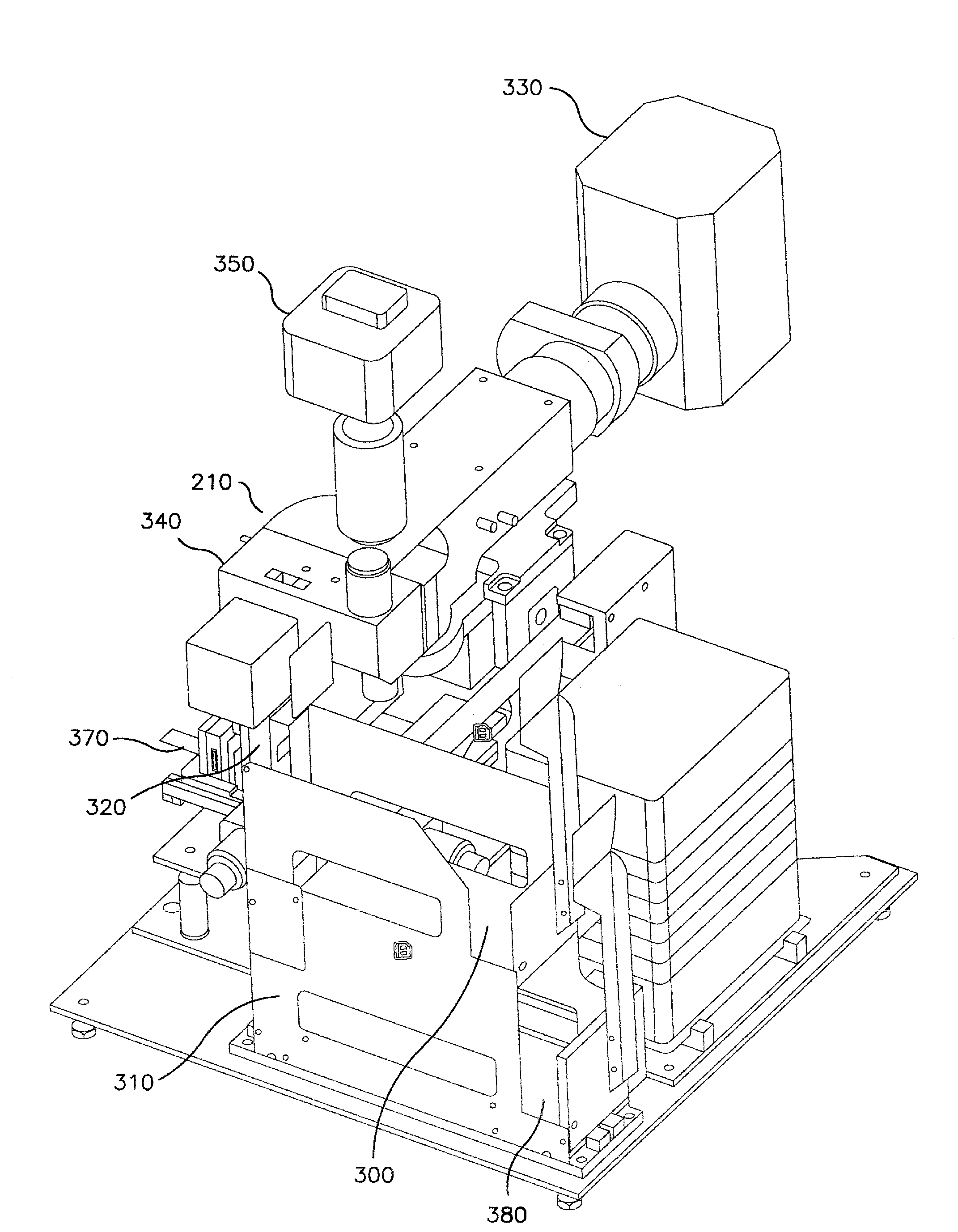
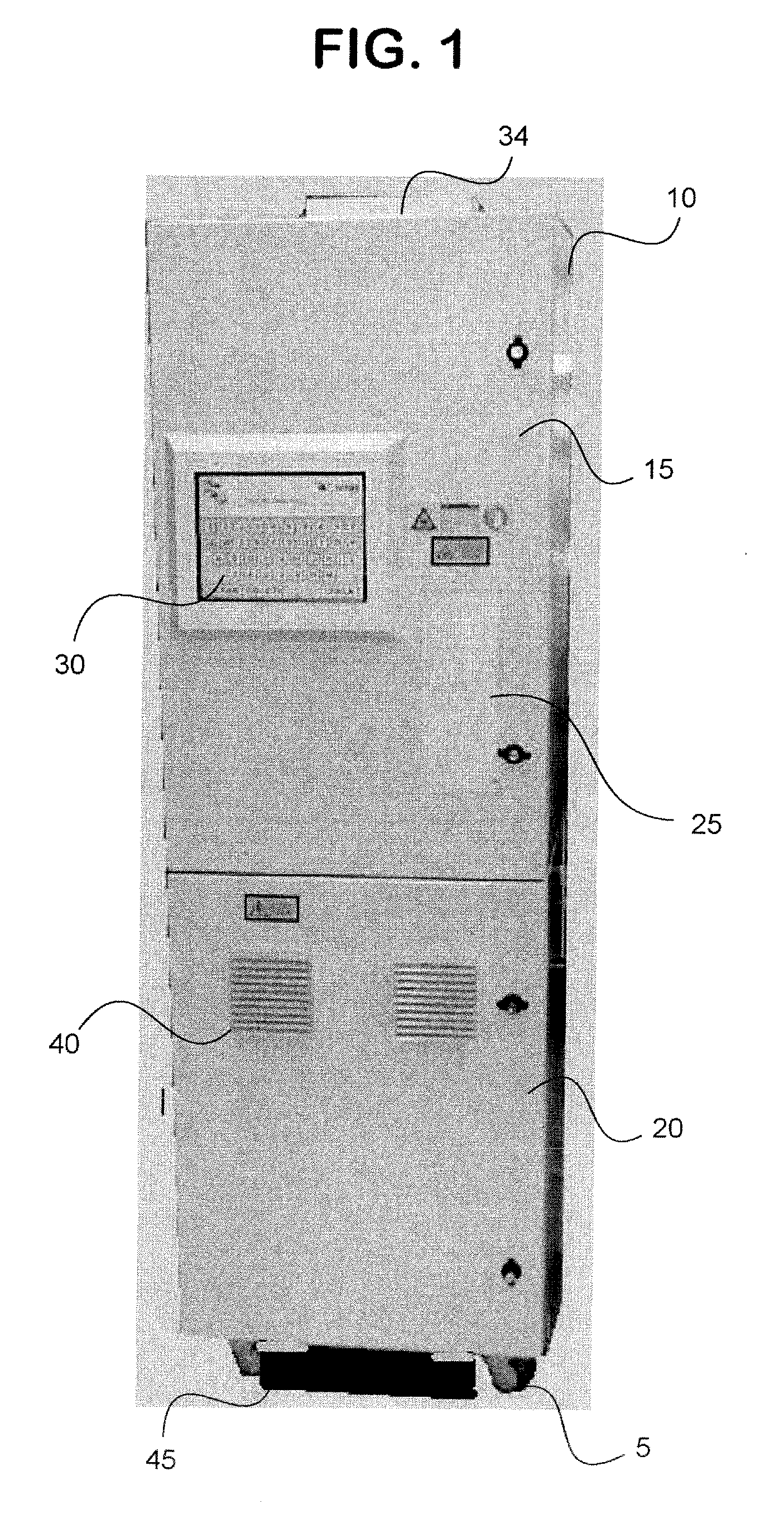
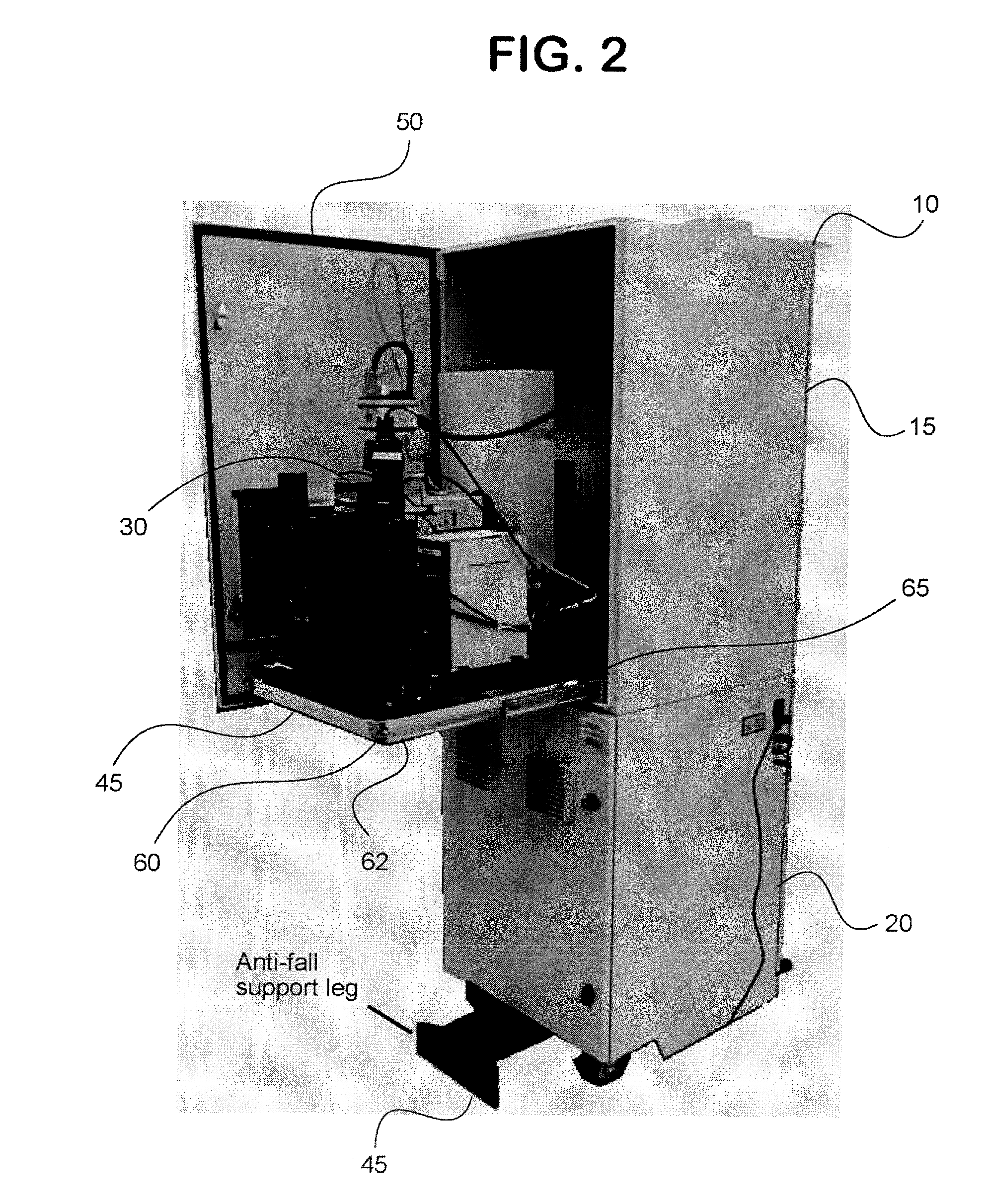
[0044]There is provided herein an integrated microscope within a light-resistant disclosure. In particular there is provided in an embodiment, an automation robotic microscope system in a light-tight enclosure positioned on movable fixtures, such as casters. Such embodiments allow for the microscope to be easily moved, and allows the microscope to work in a dark environment once the enclosure door is closed. The enclosure may further be manufactured from materials that help block harmful UV and other radiation.

[0045]In one embodiment, the enclosure further includes a filtering system that allows for the enclosed microscope to work in a clean environment.

[0046]In another embodiment, the enclosure is designed such that a surface of the enclosure that is not internal to the enclosure provides for a monitor affixed thereto, that permits viewing of information pertaining to the samples being viewed with the enclosure by the microscope system. Optionally, such monitor may include a touch ...


PUM


Abstract

A light-tight enclosure system for housing an automated microscope.

Description

CROSS-REFERENCE TO RELATED APPLICATIONS[0001]This application claims priority from U.S. Provisional Application No. 60 / 821,544, filed Aug. 4, 2006.BACKGROUND OF THE INVENTION[0002]All references cited in this specification, and their references, are incorporated by reference herein where appropriate for teachings of additional or alternative details, features, and / or technical background.FIELD OF THE INVENTION[0003]The present invention generally relates to a microscope enclosure system.DESCRIPTION OF THE RELATED ART[0004]Generally, high-end microscopes are put into darkrooms to reduce interference with viewing due to ambient light. Such microscopes are often put on tables or desks with various computer, controllers and other components which are associated therewith. While such accommodations significantly aid in microscopy, the use of dark rooms suffers from disadvantages.[0005]An initial disadvantage of any dark room is that it requires that the user of the room take time to adap...

Claims


Application Information

Patent Timeline
Patent Type & Authority Applications(United States)
IPC IPC(8): G02B21/00
CPCG02B21/24G02B21/00
Inventor TAFAS, TRIANTAFYLLOSAGARWAL, YASHKIM, YOUNGMINGUO, WEIEBERLE, RICHARDTURGEON, JOSEPHKILPATRICK, MICHAELTSIPOURAS, PETROS
Owner IKONISYS INC
Learn More