Apparatus, system and method for a ups

a technology of ups and apparatuses, applied in the direction of emergency power supply arrangements, dc source parallel operation, transportation and packaging, etc., can solve the problems of not being able to independently turn off power to a single receptacle outlet, unable to individually communicate with a plurality of electrical loads, and unable to independently control the ups

Active Publication Date: 2009-10-08
SCHNEIDER ELECTRIC IT CORP
View PDF14 Cites 46 Cited by
  • Summary
  • Abstract
  • Description
  • Claims
  • Application Information

AI Technical Summary

Benefits of technology

[0006]As outlined above, prior approaches provide a single shutdown configuration and do not allow the UPS to independently control the switched receptacle outlets. That is, the communication device may provide the UPS with a signal indicating that all of the connected loads are ready to be shutdown. The UPS can then turnoff power supplied to the receptacle outlets. Thus, prior systems are unable to individually communicate with a plurality of electrical loads and are therefore unable to independently turn off power to a single receptacle outlet or group of receptacle outlets. Instead, these prior systems turn off power to all the switched receptacle outlets (or groups of receptacle outlets) included in the UPS.

Problems solved by technology

As outlined above, prior approaches provide a single shutdown configuration and do not allow the UPS to independently control the switched receptacle outlets.
Thus, prior systems are unable to individually communicate with a plurality of electrical loads and are therefore unable to independently turn off power to a single receptacle outlet or group of receptacle outlets.

Method used


Image

  • Apparatus, system and method for a ups
  • Apparatus, system and method for a ups
  • Apparatus, system and method for a ups

Examples


Embodiment Construction

[0016]This invention is not limited in its application to the details of construction and the arrangement of components set forth in the following description or illustrated in the drawings. The invention is capable of other embodiments and of being practiced or of being carried out in various ways. Also, the phraseology and terminology used herein is for the purpose of description and should not be regarded as limiting. The use of “including,”“comprising,” or “having,”“containing”, “involving”, and variations thereof herein, is meant to encompass the items listed thereafter and equivalents thereof as well as additional items.

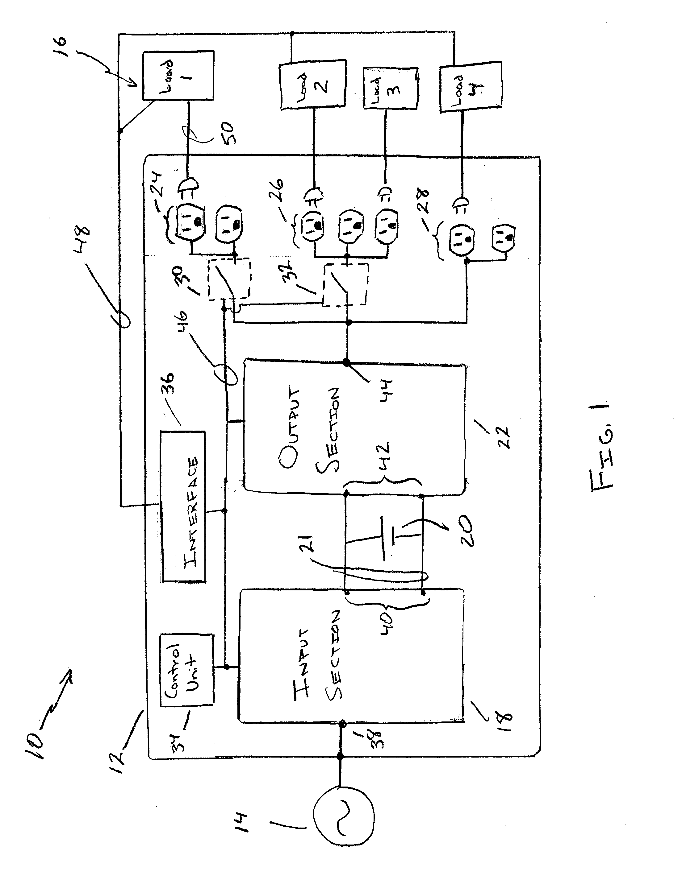
[0017]FIG. 1 illustrates a system 10 in accordance with one embodiment. The system includes a UPS 12, an AC power source 14, and electrical load 16. In the illustrated embodiment, the UPS 12 includes an input section 18, a battery 20, and an output section 22. In addition, the UPS includes a first receptacle outlet 24, a second receptacle outlet 26, and a third...


PUM


Abstract

According to one aspect of the invention, a UPS includes an input configured to be coupled to an AC power source, a DC power source, an output configured to receive power from at least one of the AC power source and the DC power source, a first switched receptacle outlet coupled to the output and configured to be coupled to a first electrical load and a second receptacle outlet coupled to the output and configured to be coupled to a second electrical load. According to some embodiments, the UPS also includes a control unit configurable to provide a first configuration associated with the first switched receptacle outlet, where the first configuration is employed by the control unit to control a connection of the first switched receptacle outlet to the output independent of the second receptacle outlet.

Description

BACKGROUND OF INVENTION[0001]1. Field of Invention[0002]Embodiments of the invention relate to uninterruptible power supplies. More specifically, at least one embodiment relates to an apparatus, system and method for independently controlling the power outlets of a UPS.[0003]2. Discussion of Related Art[0004]At present, uninterruptible power supplies (“UPS”) sometimes include one or more receptacle outlets that can be isolated by the UPS, for example, to shut down a connected load before the batteries of the UPS are fully discharged. Other UPSs may isolate one or more receptacle outlets when the load supplied from a master outlet which is not switched is reduced below a minimum value. Other UPSs employ a serial communication network to provide a UPS with an indication that loads connected to a plurality of receptacle outlets have been shut down so that the UPS can then shut down itself. However, such an approach treats a plurality of receptacle outlets and the corresponding pluralit...

Claims


Application Information

Patent Timeline
Patent Type & Authority Applications(United States)
IPC IPC(8): H02J9/00
CPCG06F1/30H02J7/0068H02J9/062
Inventor COHEN, DANIEL C.COLUCCI, DAVID A.MELANSON, MARK R.SPITAELS, JAMES S.
Owner SCHNEIDER ELECTRIC IT CORP
Why Eureka
Try Eureka