Wiring Assembly And Method For Positioning Conductor In A Channel Having A Flat Surface Portion

a technology of wire assembly and conductor, which is applied in the field of electrical systems, can solve the problems of affecting the deployment of these and other charged particle beam systems, and limiting the availability of these applications. reliability of these magnets is sometimes problematic, and the effect of beam acceleration, steering and focusing equipment, and large system size and cos

Inactive Publication Date: 2009-10-08
ADVANCED MAGNET LAB
View PDF10 Cites 19 Cited by
  • Summary
  • Abstract
  • Description
  • Claims
  • Application Information

AI Technical Summary

Problems solved by technology

System size and cost severely limit availability of these applications.
Generally, a major impediment to further deployment of these and other charged particle beam systems is the size and cost of the beam acceleration, steering and focusing equipment.
However, reliability of these magnets is sometimes problematic because the well-known phenomenon of quenching (when the superconducting material transitions to a normal, non-superconducting state) can result in rapid formation of a high temperature hot spot which can destroy a magnet.
Designs which improve reliability hav...

Method used


Image

  • Wiring Assembly And Method For Positioning Conductor In A Channel Having A Flat  Surface Portion
  • Wiring Assembly And Method For Positioning Conductor In A Channel Having A Flat  Surface Portion
  • Wiring Assembly And Method For Positioning Conductor In A Channel Having A Flat  Surface Portion

Examples


Embodiment Construction

[0021]Before describing in detail the particular methods and apparatuses related to embodiments of the invention, it is noted that the present invention resides primarily in a novel and non-obvious combination of components and process steps. So as not to obscure the disclosure with details that will be readily apparent to those skilled in the art, certain conventional components and steps have been omitted or presented with lesser detail, while the drawings and the specification describe in greater detail other elements and steps pertinent to understanding the invention. Further, the following embodiments do not define limits as to structure or method according to the invention, but only provide examples which include features that are permissive rather than mandatory and illustrative rather than exhaustive.

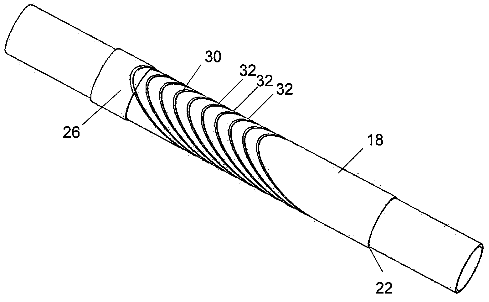
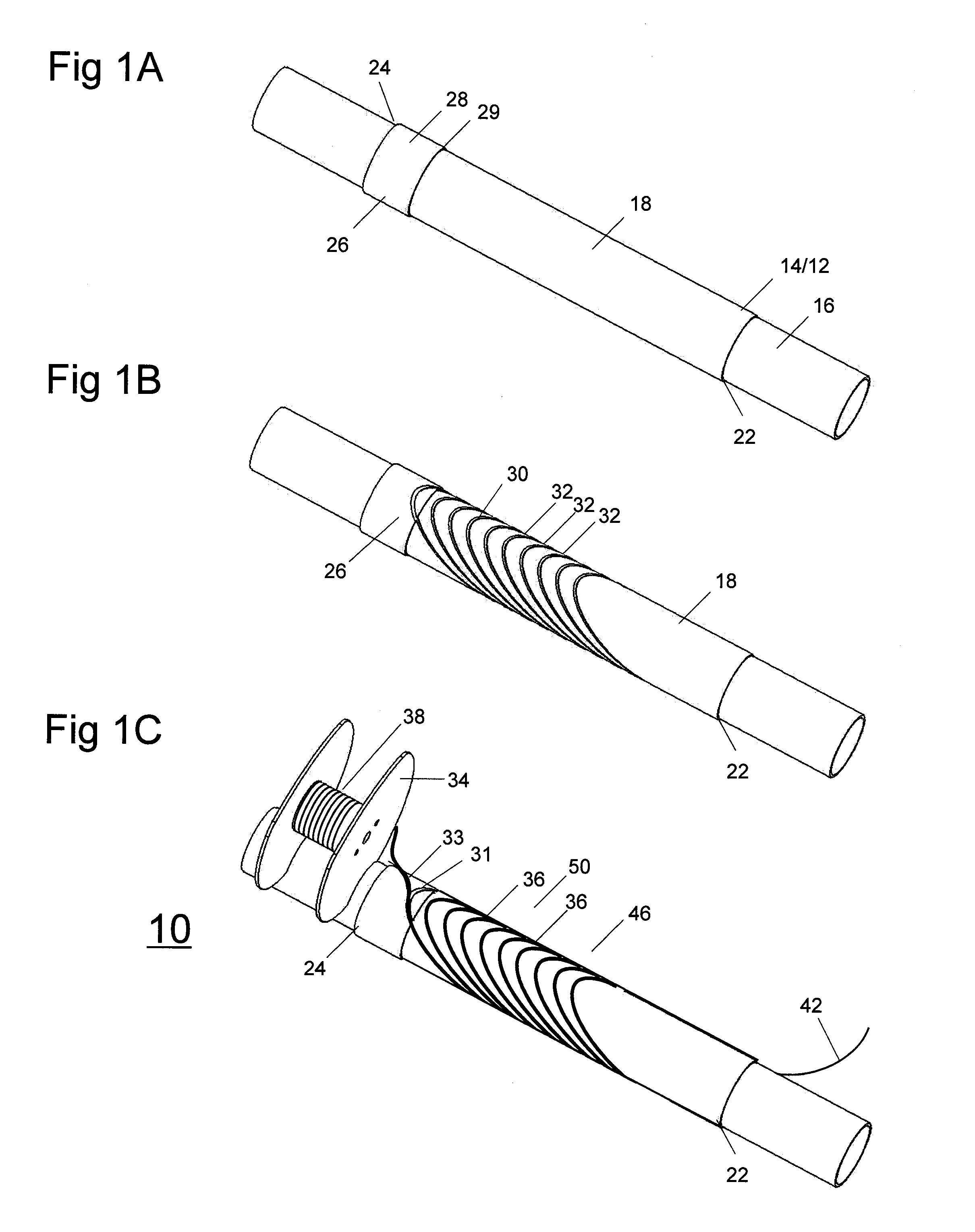
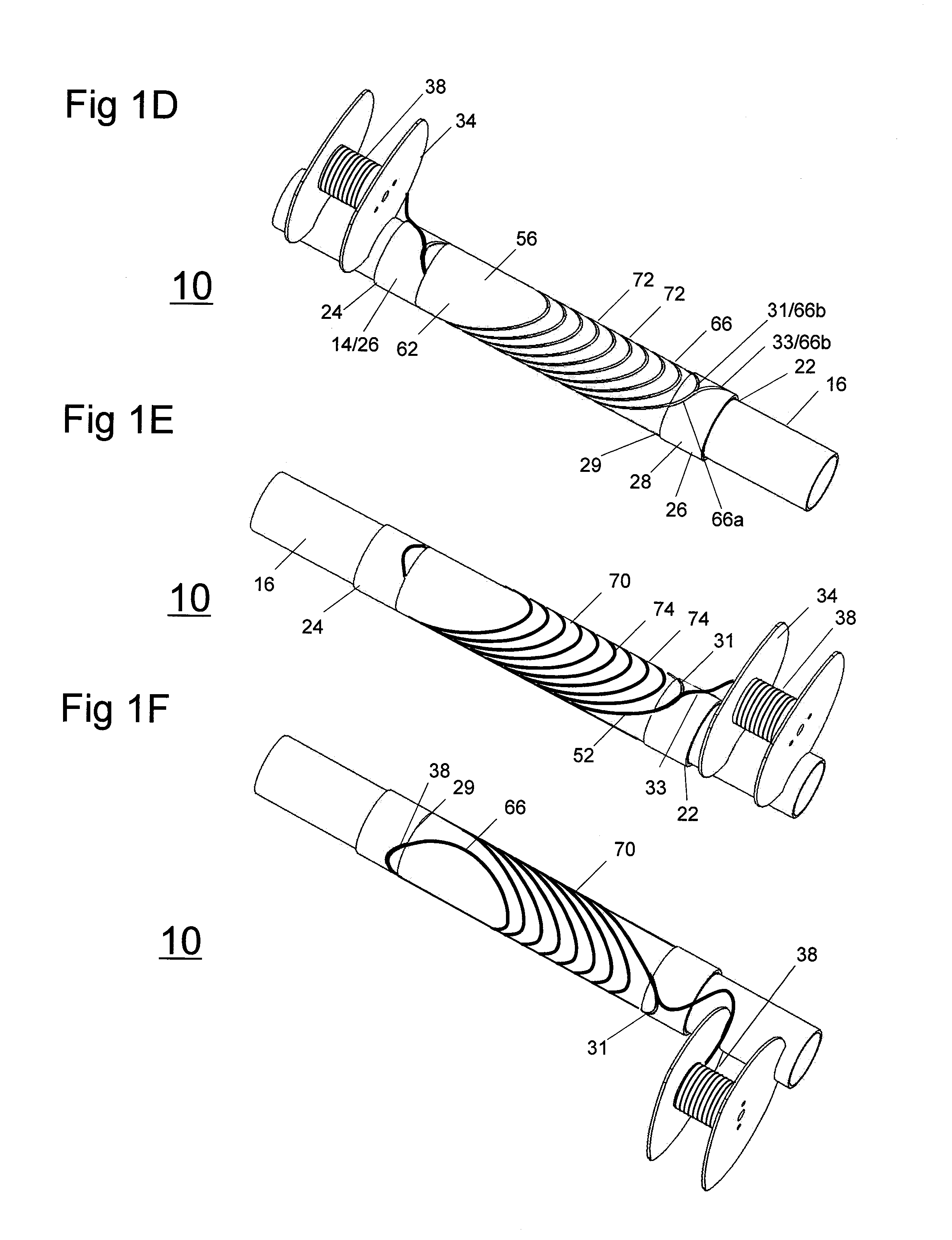
[0022]The concept of using pairs of helically-wound, concentrically positioned coils with opposite tilt angles to produce a magnetic field has been described in U.S. Pat. No. 6,...


PUM

PropertyMeasurementUnit
Lengthaaaaaaaaaa
Angleaaaaaaaaaa
Shapeaaaaaaaaaa

Abstract

A conductor assembly and method for constructing an assembly of the type which, when conducting current, generates a magnetic field or which, in the presence of a changing magnetic field, induces a voltage. In one embodiment the method includes providing a first insulative layer having a curved surface along which a conductor segment may be positioned, and forming a channel in the insulative layer, which defines a first conductor path. The channel includes first and second opposing channel surfaces each extending from the surface of the insulative layer into the insulative layer and a third channel surface extending between the first and second channel surfaces. Each of the first and second channel surfaces includes a substantially flat surface portion with the surface portion of the first channel surface parallel with the surface portion of the second channel surface. A first segment of conductor is placed in the channel.

Description

STATEMENT REGARDING FEDERALLY SPONSORED RESEARCH AND DEVELOPMENT[0001]The United States Government may have certain rights in this invention pursuant to U.S. Government Contract Number DE-FG02-06ER84492 awarded by the United States Department of Energy.FIELD OF THE INVENTION[0002]This invention relates to electromagnetic systems, including systems which generate magnetic fields, systems which generate electric power, motors, and magnets generally. More particularly, the invention relates to systems of the type including conductor assemblies which, when conducting current, generate a magnetic field or which, in the presence of a changing magnetic field, induces a voltage.[0003]It is of continued importance across many business sectors of the economy (e.g., R&D, power generation, motors and medical applications) to achieve improved performance in magnetic conductor assemblies. Development of new and improved commercial applications is dependent on an ability to create large and unifor...

Claims


Application Information

Patent Timeline
IPC IPC(8): H01F27/30H01F7/06
CPCG01R33/3804G01R33/381Y10T29/49071H01F6/06H01F41/0687G01R33/3815H01F41/098
Inventor STELZER, GERALDMEINKE, RAINERSENTI, MARK
Owner ADVANCED MAGNET LAB
Why Eureka
Try Eureka