Method and related circuit for color depth enhancement of displays

a color depth enhancement and related circuit technology, applied in static indicating devices, cathode-ray tube indicators, instruments, etc., can solve the problems of difficult to achieve smooth and natural color dithering, and affecting the effect of color depth enhancemen

Inactive Publication Date: 2009-10-08
FARADAY TECH CORP
View PDF9 Cites 15 Cited by
  • Summary
  • Abstract
  • Description
  • Claims
  • Application Information

AI Technical Summary

Benefits of technology

[0015]Basically, line values and pixel values are used to control spatial pattern of color channel selection; with help of LUT values corresponding to frame counts in temporal domain, color channel selection for each pixel is determined. Because line values (as well as pixel values) and frame counts are provided with stochastic nature, a random temporal dithering order and a random spatial dithering pattern are introduced in color dithering of the present invention, such that visual discomfort and artifacts caused by regular (and deterministic) dithering patterns of prior arts can be reduced and / or avoided.

Problems solved by technology

However, the aforementioned prior arts have similar disadvantages.
While enhancing color depth between two displayable color levels (r0, g0, b0) and (r1, g1, b1), those arts directly display the two extreme color levels (r0, g0, b0) and (r1, g1, b1) in an alternating manner; since the two color levels (r0, g0, b0) and (r1, g1, b1) have large mutual contrast, a smooth and natural color dithering is difficult to achieve.
Also, while those arts use regularly repeated alternating temporal and spatial patterns to display the two extreme color levels for color dithering, the regularly repeated patterns often demonstrate uncomfortable flickers in human vision.
For example, in FIG. 2, regularly repeated patterns of alternating extreme color levels in both temporal and spatial domains will cause microscopic oblique line patterns tilted in alternating directions, which is difficult to achieve a steady and comfortable color dithering and color depth enhancement.

Method used


Image

  • Method and related circuit for color depth enhancement of displays
  • Method and related circuit for color depth enhancement of displays
  • Method and related circuit for color depth enhancement of displays

Examples


Embodiment Construction

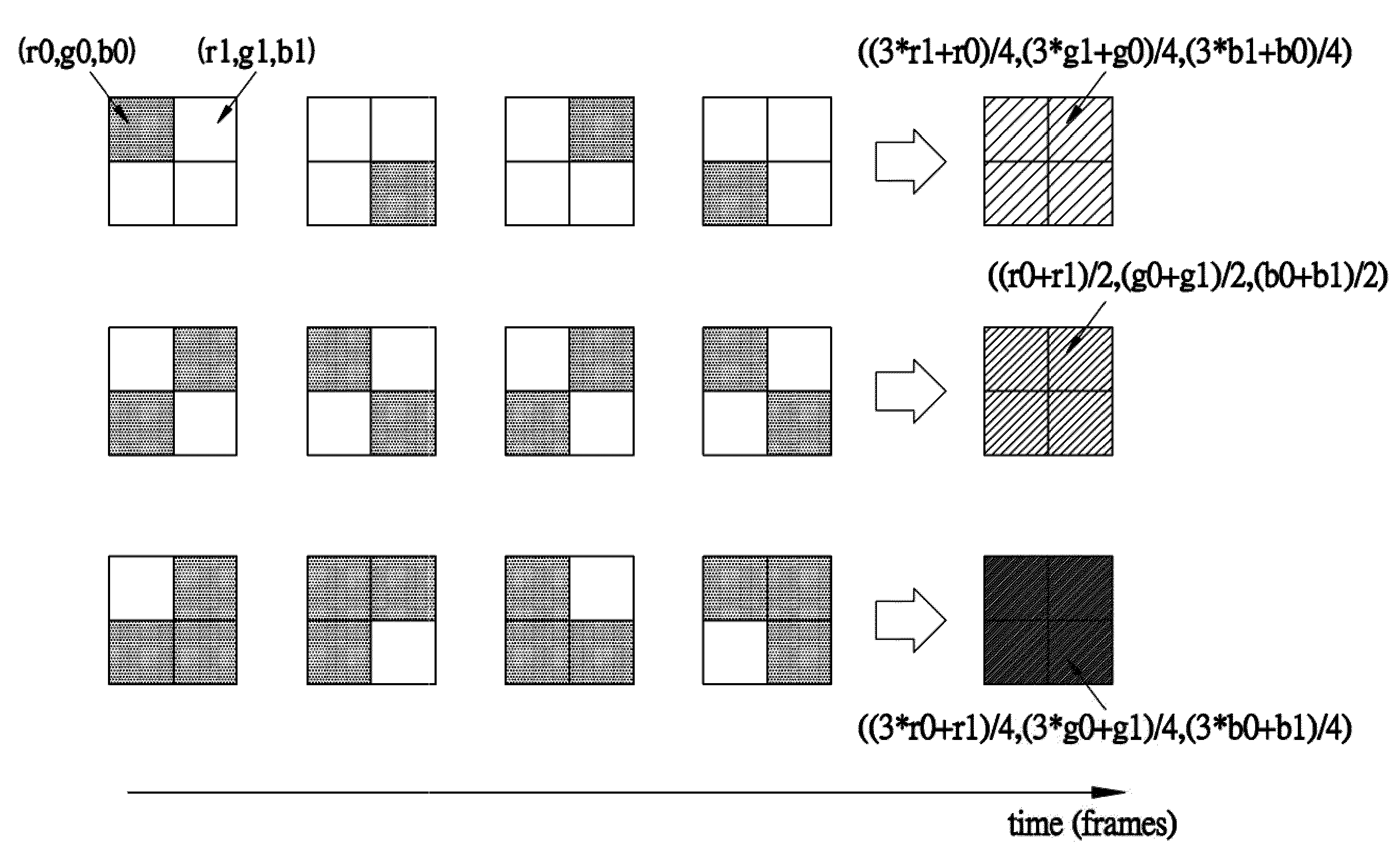
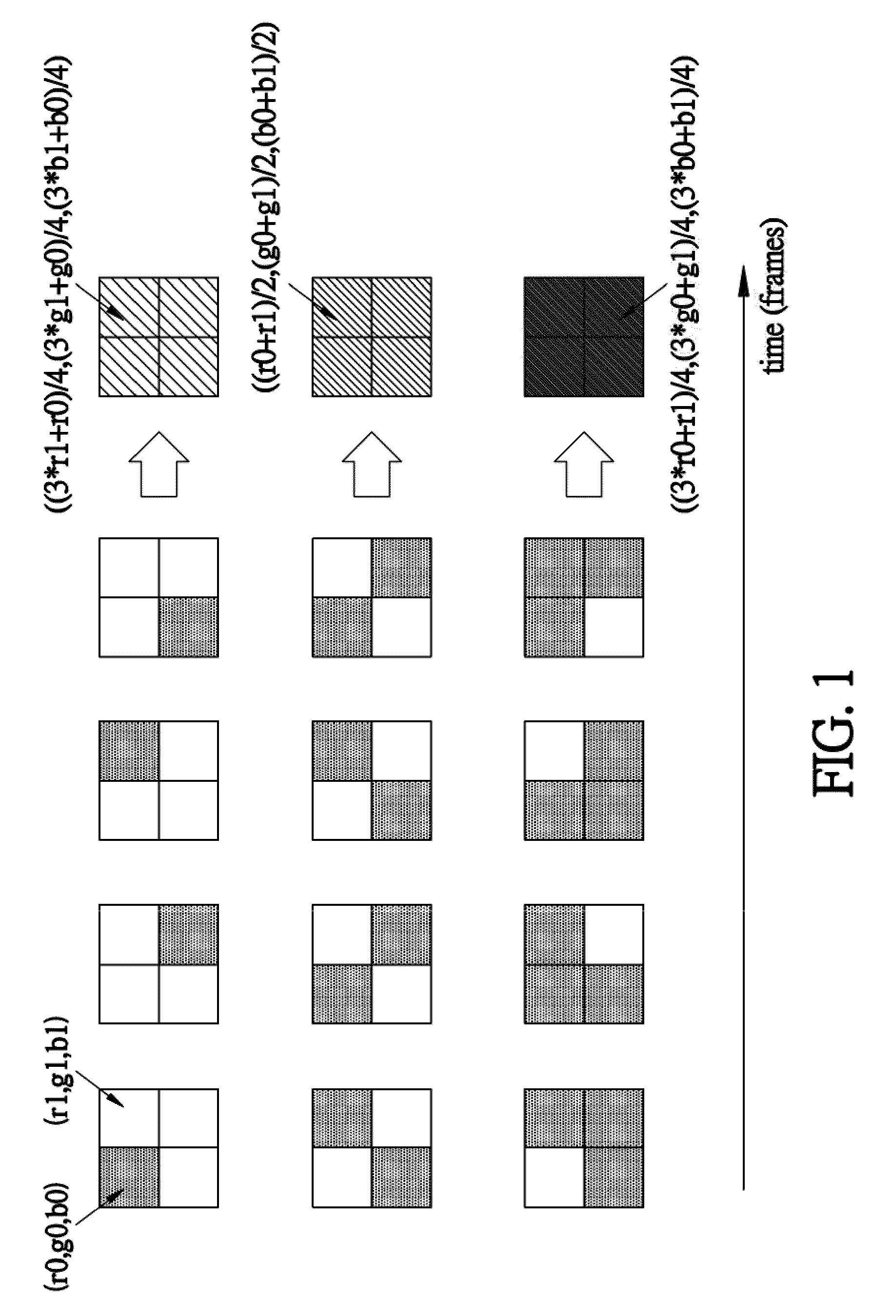
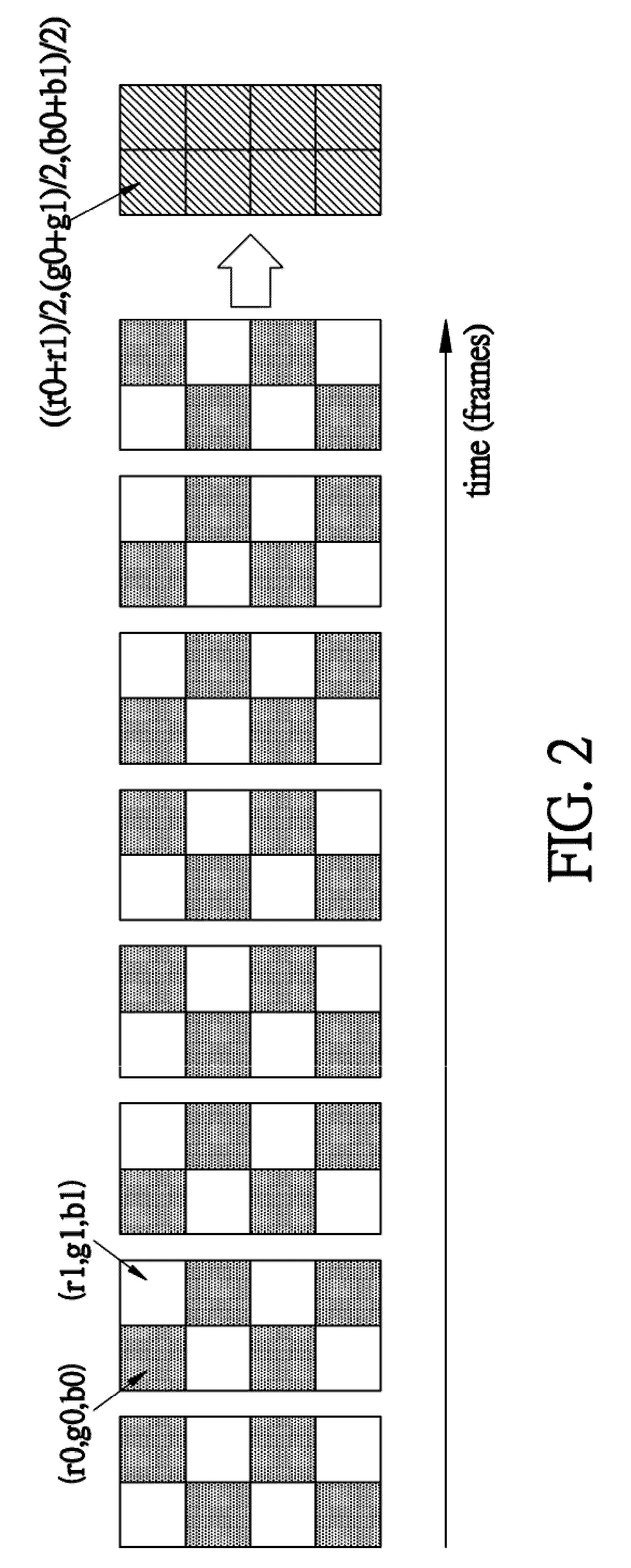
[0034]Please refer to FIG. 3 which depicts an exemplary embodiment to illustrate technique and advantage of the present invention comparing to prior art. As previously discussed, assuming a display / display panel can display two (displayable) color levels (r0, g0, b0) and (r1, g1, b1), a prior art directly displays these two color level in alternating manner to emulate a color level not displayable, as shown in upper portion of FIG. 3. On the other hand, in one embodiment of the invention, color levels (r0, g1, b0), (r1, g0, b1) and (r0, g0, b0) are adopted for color depth enhancement (though color level (r1, g1, b1) can also be used, as detail will be discussed later), as shown in lower portion of FIG. 3. The prior art and the invention both emulate a color level not displayable (a color level (3*r0+r1) / 4, (3*g0+g1) / 4, (3*b0+b1) / 4) in the example of FIG. 3). However, since the prior art uses two extreme color levels (r0, g0, b0) and (r1, g1, b1) which have large mutual contrast for ...


PUM


Abstract

Method and related circuit for color depth enhancement of displays is provided. In an embodiment of the invention, when emulating an interpolated color level between a first and a second color levels the display can display, a color channel component of the first color level and another color channel component of the second color level are selected for color dithering and color depth enhancement.

Description

FIELD OF THE INVENTION[0001]The present invention relates to a method and related circuit for color depth enhancement of displays, and more particularly, to a method and related circuit for color depth enhancement using alternating components of different color channels.BACKGROUND OF THE INVENTION[0002]Displays, especially liquid crystal displays (LCD's), are one of the most important human-machine interfaces of modern information system. Thus, how to enhance display functions of displays has become a technology development key point of modern information system designers and vendors.[0003]As known by those skilled in art, color display capability of a display panel (like an LCD panel) in a display is usually presented as number of bits of displayable color levels. For example, a 6-bit display panel means that the display panel can display 2̂6 (=128) different levels in each of red, green and blue channels, i.e., a 6-bit display panel can display 2̂18 different color levels in total...

Claims


Application Information

Patent Timeline
Patent Type & Authority Applications(United States)
IPC IPC(8): G09G5/02
CPCG09G3/2055
Inventor HSU, CHING-HSIANGLU, LING-CHIHCHEN, TANG-WEI
Owner FARADAY TECH CORP
Why Eureka
Try Eureka