
Lamp Assembly

Inactive Publication Date: 2009-10-08
MYLAR ELECTRONICS
View PDF3 Cites 1 Cited by
  • Summary
  • Abstract
  • Description
  • Claims
  • Application Information

AI Technical Summary

Benefits of technology

[0006]A primary objective of the present invention is to provide a lamp assembly having a light module and a stem, which is easy to repair and can prevent wire twisting inside the stem.
[0007]Accordingly, the light module comprising a first fixing plate, a second fixing plate mounted on the first fixing plate and having a plurality of fixing pieces pivotally connected on a periphery of the second fixing plate, a reflector having an opening for allowing the second fixing plate to pass through and fixed between the first fixing plate and the second fixing plate by the fixing pieces, an electronic ballast disposed on the second fixing plate, and a lamp disposed on the electronic ballast. By rotating the fixing pieces, the reflector can be easily disassembled from and assembled with the light module without disassembling the whole light module. The stem comprises a plurality of connecting tubes and a plurality of connecting assemblies connecting the connecting tubes, in which each connecting assembly has a male joint with an L-shape projection at one end, a female joint with an L-shape slot at one end corresponding to the L-shape projection of the male joint, and a decoration ring arranged between the male joint and female joint. It only needs to make a small rotation to engage the male joint with the female joint, and therefore it prevents the wire twisting inside the stem.
[0008]The male joint according to the present invention has a plurality of external vertical ridges formed at the opposite end of the L-shape projection for engaging with a plurality of internal vertical grooves of the connecting tube. The male joint is directly fitted into the connecting tube without rotation, and therefore it prevents the wire twisting inside the stem.
[0009]The female joint according to the present invention has external vertical ridges at the external surface for engaging with a plurality of internal vertical grooves of the connecting tube. The female joint is directly fitted into the connecting tube without rotation, and therefore it prevents the wire twisting inside the stem.

Problems solved by technology

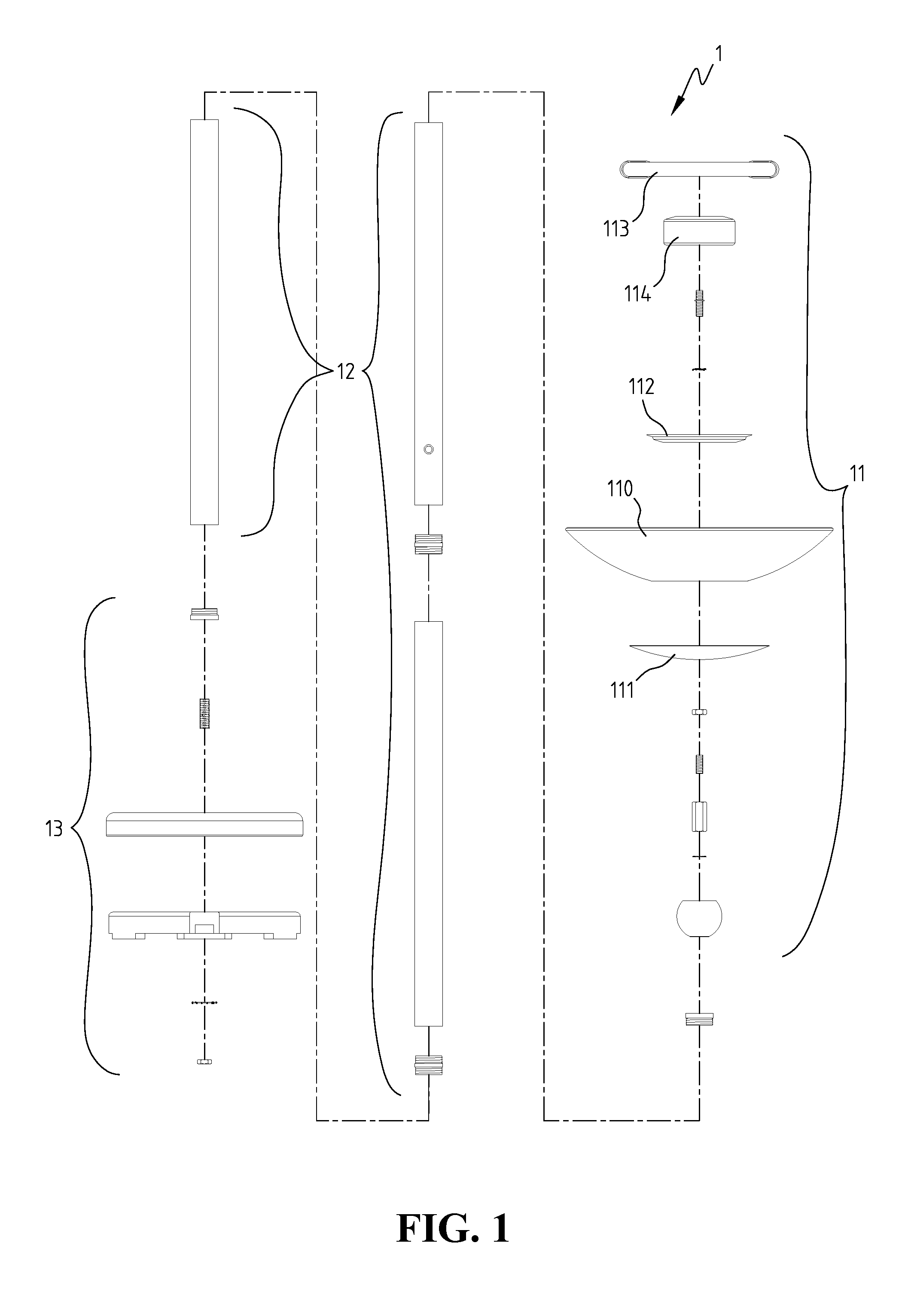
Each component of the light source 11 has to be disassembled from the light source 11 and reassembled together again after replacing a new reflector, which complicates the repair and will cost a lot of time.

Method used


Image

  • Lamp Assembly
  • Lamp Assembly
  • Lamp Assembly

Examples


Embodiment Construction

[0017]Referring to FIG. 3, a lamp assembly 3 in accordance with an embodiment of the present invention comprises a light module 31, a stem 33 having an end coupled to the light module 31, and a base 35 coupled to the other end of the stem 33.

[0018]Referring to FIG. 4, the light module 31 comprises a first fixing plate 313, a second fixing plate 315 mounted on the first fixing plate 313 and having three fixing pieces 317 pivotally connected on a periphery of the second fixing plate 315, an electronic ballast 319 mounted on the second fixing plate 315, a reflector 310 having an opening 311 for allowing the second fixing plate 315 to pass through and fixed between the first fixing plate 313 and the second fixing plate 315 by the fixing pieces 317, a lamp 318 disposed on the electronic ballast 319. An inner diameter of the opening 311 of the reflector 310 is slightly greater than the outer diameter of the second fixing plate 315 and smaller than the outer diameter of the first fixing pl...


PUM


Abstract

A lamp assembly includes a light module and a stem. The light module includes a reflector, a first fixing plate, a second fixing plated mounted on the first fixing plate and having a plurality of fixing pieces pivotally connected thereon for fixing the reflector between the first fixing plate and the second fixing plate, and a lamp. By rotating the fixing pieces, the reflector is easy to replace. The stem includes a plurality of connecting tubes and connecting assemblies. Each connecting assembly has a male joint with an L-shape projecting and a female joint with an L-shape slot. The male joint is fitted into the connecting tube, and the female joint is fitted into another connecting tube. By engaging the L-shape projection with the L-shape slot, the two connecting tubes can be connected without twisting a wire inside the stem.

Description

BACKGROUND OF THE INVENTION[0001]1. Field of the Invention[0002]The present invention generally relates to a lamp assembly, and in particular to a lamp assembly which is easy to repair and can prevent wire twisting inside a lamp stem.[0003]2. The Prior Arts[0004]Referring to FIG. 1, a conventional lamp assembly 1 comprises a light source 11, a stem 12 having an end coupled to the light source 11, and a base 13 coupled to the other end of the stem 12. The light source 11 comprises a reflector 110, a first fixing plate 111 mounted to a first end of the reflector 110 and a second fixing plate 112 mounted to a second end of the reflector 110 by bolts and nuts, an electronic ballast 114 fixed on the second fixing plate 112, and a lamp 113 disposed on the electronic ballast 114, in which the reflector 110 is fixed between the first fixing plate 111 and the second fixing plate 112. The conventional light source 11 has the shortcoming that it is difficult to replace the reflector 110 when t...

Claims


Application Information

Patent Timeline
IPC IPC(8): F21S8/08
CPCF21S6/007F21S8/088F21V7/0058F21V15/01F21Y2103/022F21V17/18F21V21/12F21V23/02F21V17/08F21Y2103/33
Inventor CHENG, TE-CHANG
Owner MYLAR ELECTRONICS
Learn More