System and method for surgical jaw assembly

a surgical and jaw assembly technology, applied in the field of surgical jaw assembly, can solve the problems of inefficient and expensive addition of custom stop surfaces, increased manufacturing time and costs, and increased manufacturing costs, so as to achieve the desired pressure and gap distance for procedures, and the effect of precise surgical jaw assembly

Inactive Publication Date: 2009-10-08
CREGANNA UNLTD
View PDF3 Cites 70 Cited by
  • Summary
  • Abstract
  • Description
  • Claims
  • Application Information

AI Technical Summary

Benefits of technology

[0009]An advantage of the present invention is the omission of adhesives or fasteners from the assembly to secure the components to one another, thereby producing a precise surgical jaw assembly that is capable of providing the desired pressure and gap distance for procedures.
[0010]Yet another advantage of the present invention is the use of injection molding to manufacture the components, thereby creating more uniformity and precision with multiple surgical jaw assemblies.
[0011]Still another advantage of the present invention is the use of a stop surface or other feature that is integrated into the surgical jaw assembly, thereby creating more uniformity and precision in the gap distance of surgical jaw assemblies.

Problems solved by technology

Due to the inherent spatial considerations of the surgical cavity, surgeons often have difficulty suturing vessels or performing other traditional methods of controlling bleeding, e.g., clamping and / or tying-off transected blood vessels.
The addition of the custom stop surface is inefficient and expensive.
The premolded datum adds extra time and costs to manufacturing, however.

Method used


Image

  • System and method for surgical jaw assembly
  • System and method for surgical jaw assembly
  • System and method for surgical jaw assembly

Examples


Embodiment Construction

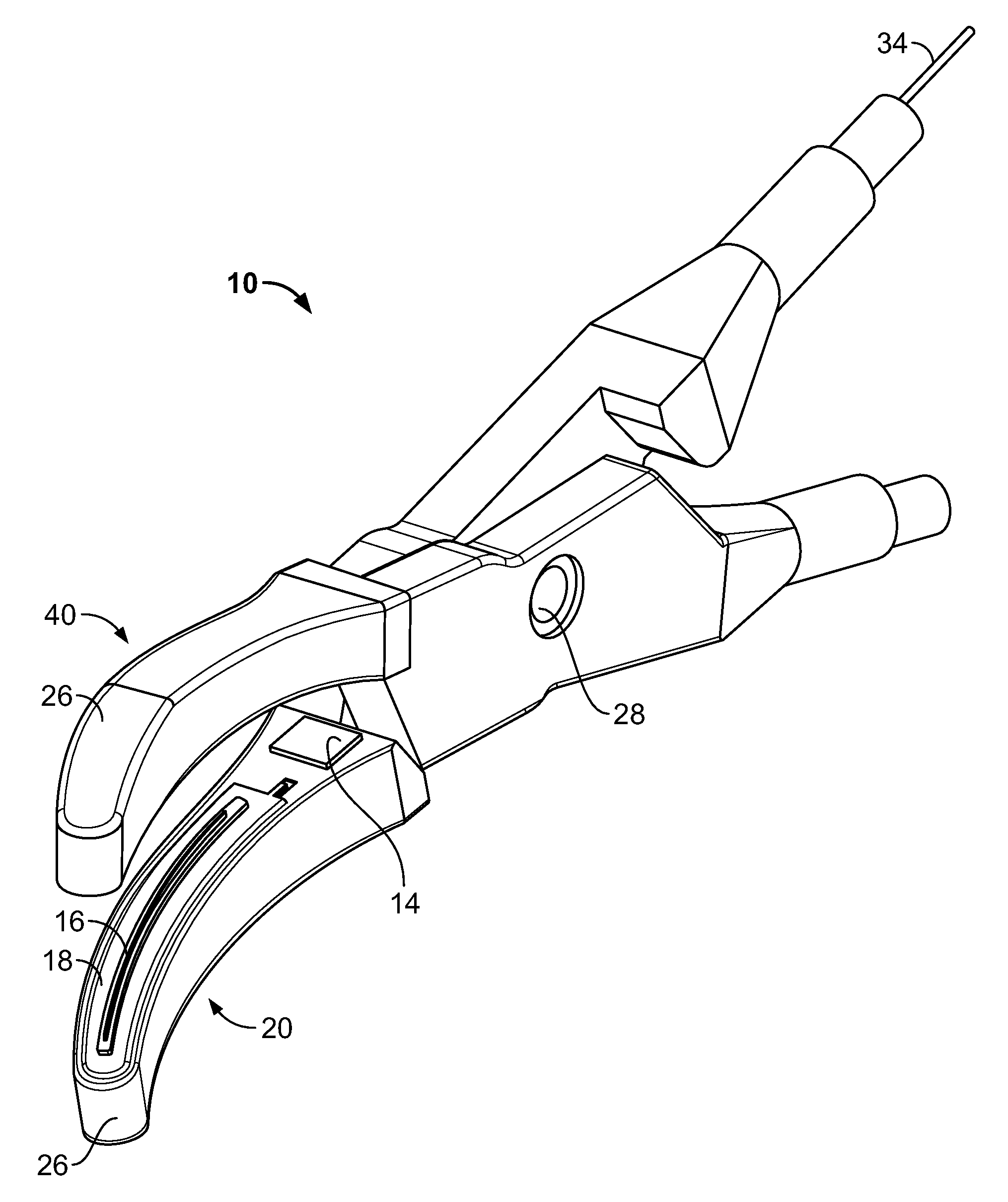
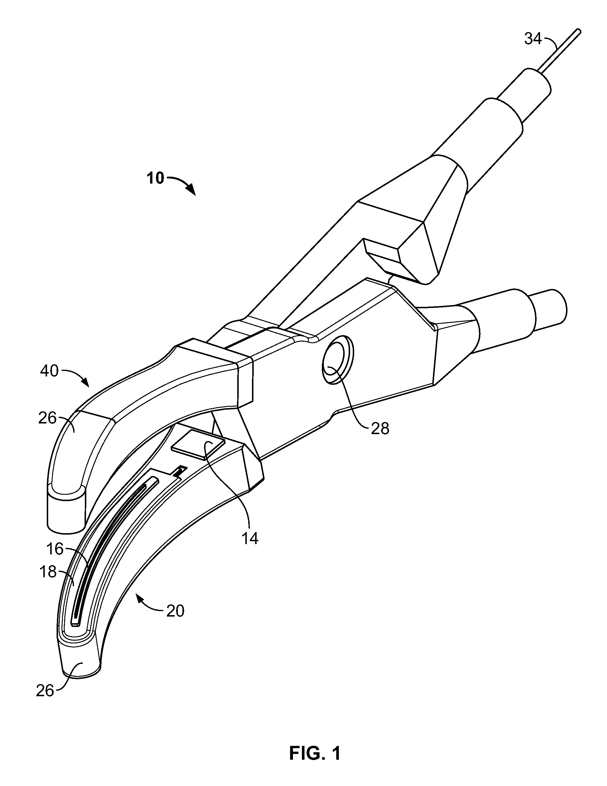
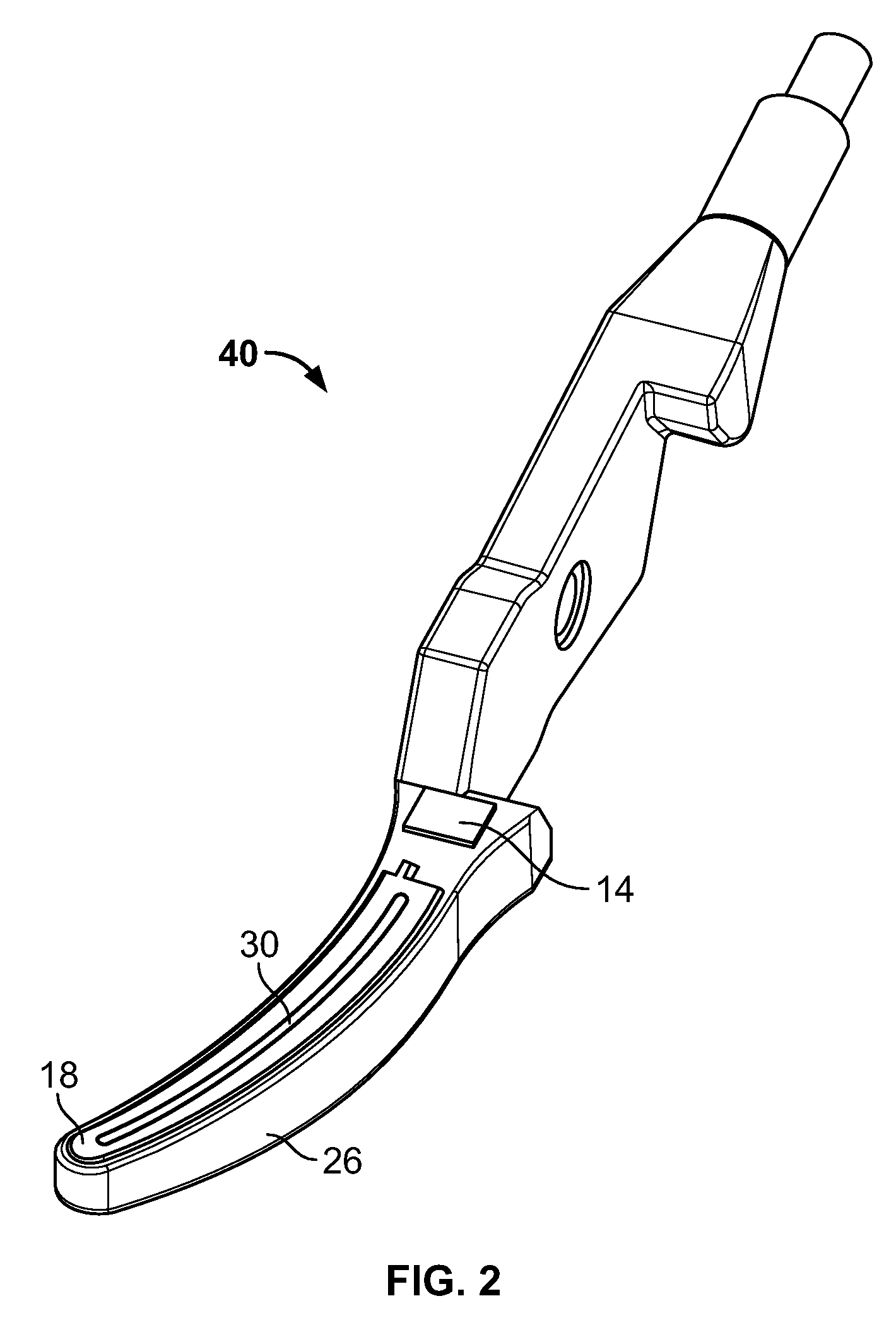
[0023]FIG. 1 shows a surgical jaw assembly 10 with a top portion 40 and bottom portion 20. Top portion 40 and bottom portion 20 are hingedly attached to one another and may rotate about a pivot point 28. A fastener or other suitable type of securing device (not shown) may be used to connect and secure top portion 40 to bottom portion 20 and allow movement about pivot point 28. Top portion 40 may extend into pivot point 28 to engage with bottom portion 20, as shown in FIG. 1. Bottom portion 20 includes a blade 16 and seal plate 18, where blade 16 protrudes through an aperture 30 (FIG. 2) in seal plate 18. Blade 16 is stationary relative to bottom portion 20 and may be an electrically charged blade. The movement of top portion 40 and bottom portion 20 about pivot point 28 facilitates the severing or cutting of vessels or tissue (not shown) by blade 16. Seal plate 18 coagulates or cauterizes the tissue or vessel on either side of the cut made by blade 16. Cauterizing by seal plate 18 s...


PUM

PropertyMeasurementUnit
thicknessaaaaaaaaaa
electricallyaaaaaaaaaa
electrically chargedaaaaaaaaaa

Abstract

A surgical jaw assembly having a top portion and a bottom portion hingedly attached. The top and bottom portion having a base, a seal plate and a cover, the seal plate and base being in direct contact and being electrically common. The bottom portion having a blade that is stationary relative to the base and the top portion having an insert configured to receive the blade when the top portion and bottom portion are in a predetermined position. The cover is overmolded onto the base, securing the seal plate to the base on both the top portion and bottom portion.

Description

FIELD OF THE INVENTION[0001]The present invention is directed to a surgical jaw assembly. More specifically, the present invention is directed to a surgical jaw assembly with an overmold.BACKGROUND OF THE INVENTION[0002]Electrosurgical forceps use both mechanical clamping action and electrical energy to affect hemostasis by heating tissue and blood vessels to coagulate, cauterize and / or seal tissue. Instruments, such as a surgical jaw, are inserted into the patient's body to facilitate various tasks during surgical procedures, such as cutting or ligating blood vessels or vascular tissue. Due to the inherent spatial considerations of the surgical cavity, surgeons often have difficulty suturing vessels or performing other traditional methods of controlling bleeding, e.g., clamping and / or tying-off transected blood vessels. By using a surgical jaw assembly, a surgeon can cauterize, coagulate / desiccate and / or reduce or slow bleeding simply by controlling the intensity, frequency and dur...

Claims


Application Information

Patent Timeline
Patent Type & Authority Applications(United States)
IPC IPC(8): A61B19/00B23P21/00
CPCA61B18/1442A61B2017/2945A61B2018/00404Y10T29/49904A61B2018/0063A61B2018/1432A61B2019/304A61B2018/00601A61B2090/034
Inventor ALLISON, JEFFREY WAYNEMILLER, KEITH EDWIN
Owner CREGANNA UNLTD
Why Eureka
Try Eureka