Top Loading Polyaxial Spine Screw Assembly With One Step Lockup

a polyaxial spine screw and lockup technology, applied in the field of screw assemblies, can solve the problems of increasing the operative time, requiring several steps to lock the various components of the current spinal rod screw assembly,

Inactive Publication Date: 2009-10-08
LIFE SPINE INC
View PDF95 Cites 194 Cited by
  • Summary
  • Abstract
  • Description
  • Claims
  • Application Information

AI Technical Summary

Benefits of technology

[0016]The present spinal rod screw assembly is formed of one or more biocompatible materials suitable for spine implants. Various sizes of the present spinal rod screw assembly are manufactured for various applications.

Problems solved by technology

However, locking of the various components of current spinal rod screw assemblies requires several steps and / or features or mechanisms thereof.
This increases operative time by the surgeon to install the spinal rod screw assembly.

Method used


Image

  • Top Loading Polyaxial Spine Screw Assembly With One Step Lockup
  • Top Loading Polyaxial Spine Screw Assembly With One Step Lockup
  • Top Loading Polyaxial Spine Screw Assembly With One Step Lockup

Examples


Embodiment Construction

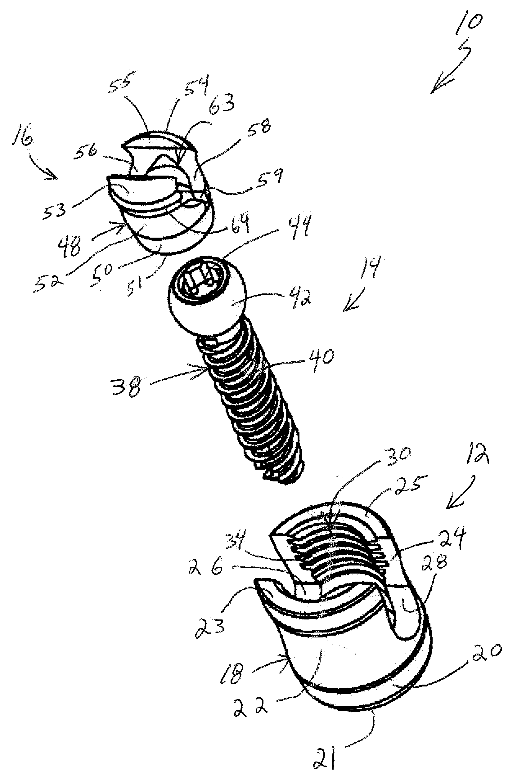
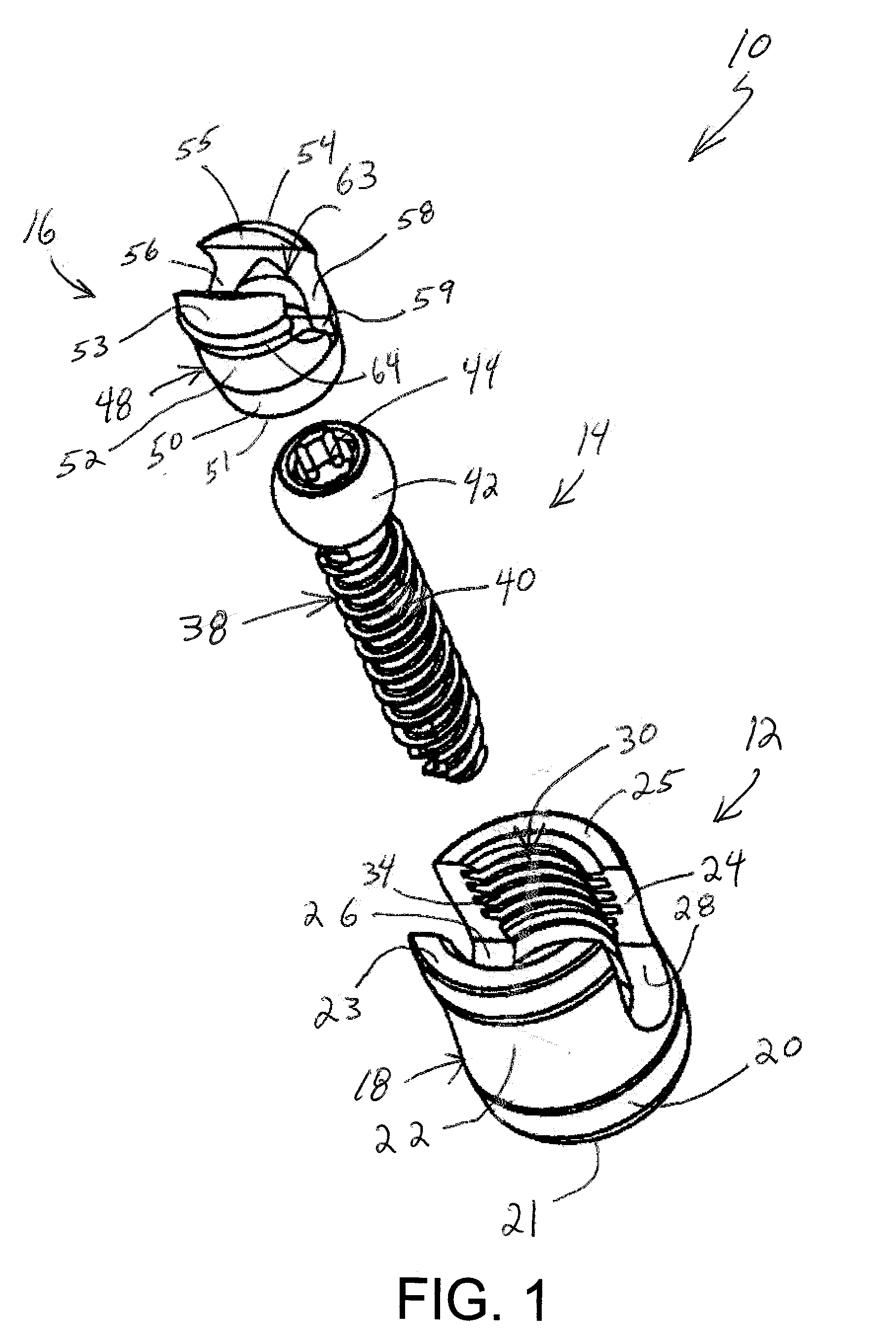
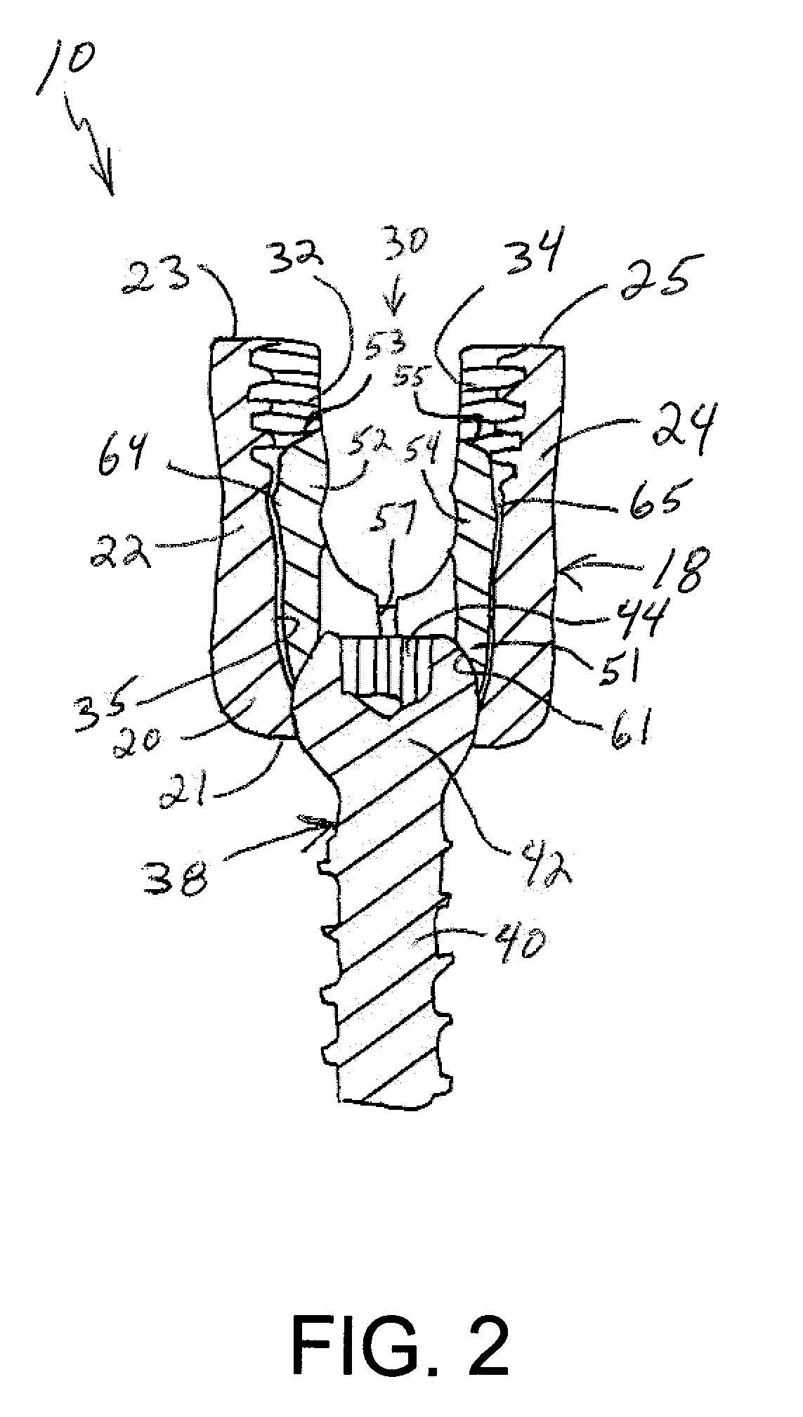
[0026]FIGS. 1 and 2 depict various views of a polyaxial spinal rod screw system or assembly 10 for holding a spinal rod relative on and to a vertebra (not shown). FIG. 1 depicts base components of the spinal rod screw assembly 10 in an exploded or pre-assembled view. FIG. 2 is a sectional view of the components of the screw assembly 10 in an assembled state. The spinal rod screw assembly 10 in one form is characterized by a rod holder, connector or head 12, an insert or collet 16, and a collar, end cap, lockup cap or the like 74. The spinal rod screw assembly in another form is characterized by a rod holder, connector or head 12, a bone screw 14, an insert 16, and a lockup cap 74 (see, e.g., FIG. 6). In another form, the spinal rod screw assembly is characterized by a rod holder, connector or head 12, an insert or collet 16, and a bone screw 14. In a further form, the spinal rod screw assembly is characterized by a rod holder, connector or head 12, an insert or collet 16, a bone scr...


PUM


Abstract

A top loading polyaxial spinal rod screw assembly is configured for simultaneous or one step lockup of angular orientation of a rod holder portion of the screw assembly relative to a bone screw and of a spinal rod within the rod holder portion of the screw assembly. The spinal rod and the angular orientation of the rod holder holding the spinal rod are thus fixed upon receipt of a lockup component of the present assembly. Components of the present spinal rod screw assembly cooperate to allow reception of a spinal rod in a rod holder that is adapted for pivotal retention on a bone screw and to lock or fix the spinal rod within the rod holder while also locking or fixing the angular orientation of the rod holder relative to the bone screw upon receipt of a lockup cap component of the screw assembly in the rod holder. In one form, the present screw assembly is defined by a three-piece polyaxial screw head assembly for a bone screw. The three-piece polyaxial screw head assembly includes a spine rod holder or head configured for pivotal connection with the bone screw, a head insert configured for reception in the spine rod holder, and a lockup (end) cap configured for reception in the spine rod holder. The lockup cap is configured to interact with the head insert to fix an angular position or orientation of the spine rod holder relative to the bone screw at the same time as fixing a spinal rod that has been received in the spine rod holder relative to the spine rod holder.

Description

RELATED APPLICATIONS[0001]This patent application claims the benefit of and / or priority to U.S. Provisional Patent Application Ser. No. 61 / 072,857 filed Apr. 3, 2008, entitled “Top Loading Polyaxial Spine Screw Assembly With One Step Lockup” the entire contents of which is specifically incorporated herein by this reference.BACKGROUND OF THE INVENTION[0002]1. Field of the Invention[0003]The present invention relates to spine fixation components, constructs and assemblies and, more particularly, to screw assemblies for spinal rod applications.[0004]2. Background Information[0005]Spinal orthopedic assemblies and constructs such as spine plates, spinal bone screw assemblies for spinal rods and other devices (spinal components) have made a profound contribution to the correction of spinal deformities, accidents and other problems in the cervical as well as thoracic, lumbar and sacral spine. These and other spinal devices are typically fixed to vertebrae using vertebral bone screws. Verte...

Claims


Application Information

Patent Timeline
Patent Type & Authority Applications(United States)
IPC IPC(8): A61B17/70A61B17/86
CPCA61B17/7037A61B17/7032
Inventor PREDICK, DANIEL
Owner LIFE SPINE INC
Why Eureka
Try Eureka