Solenoid valve

a solenoid valve and valve body technology, applied in the direction of valve operating means/releasing devices, magnets, magnetic bodies, etc., can solve the problems of increasing manufacturing costs, requiring high manufacturing costs, and complicating the manufacturing process, so as to reduce element materials, simplify manufacturing processes, and save energy

Inactive Publication Date: 2009-10-15
DELTA ELECTRONICS INC
View PDF4 Cites 11 Cited by
  • Summary
  • Abstract
  • Description
  • Claims
  • Application Information

AI Technical Summary

Benefits of technology

[0015]To solve the problems of the conventional solenoid valve, it is an object of the present invention to provide a solenoid valve with a structural design that replaces a permanent magnet and a fixing structure for maintaining the self-latch solenoid valve in a normal open or a normal closed position. Advantages of the present invention include economized energy usage, reduced element materials, simplified manufacturing processes, reduced manufacturing costs, and simplified circuit design.
[0017]For the above descriptions, the structural design of the solenoid valve of the invention including the slidable ring, the rotatable ring, the bobbin, and the guiding grooves is used to achieve the functions of a normal open and a normal closed position of the solenoid valve without the application of the permanent magnet and the fixing structure. Thus, advantages of the present invention include economized energy usage, reduced element materials, simplified manufacturing processes, and reduced manufacturing costs. Moreover, the excitation voltage is a pulse voltage to simplify the driving circuit design.

Problems solved by technology

Moreover, the solenoid valve 5 is equipped with a fixing structure 55 for fixing the permanent magnet 51, thus, requiring high manufacturing costs.
Similarly, the above-mentioned design requires more components, and therefore increases manufacturing costs and complicates the manufacturing process.

Method used


Image

  • Solenoid valve
  • Solenoid valve
  • Solenoid valve

Examples


Embodiment Construction

[0029]The following description is of the best-contemplated mode of carrying out the invention. This description is made for the purpose of illustrating the general principles of the invention and should not be taken in a limiting sense. The scope of the invention is best determined by reference to the appended claims.

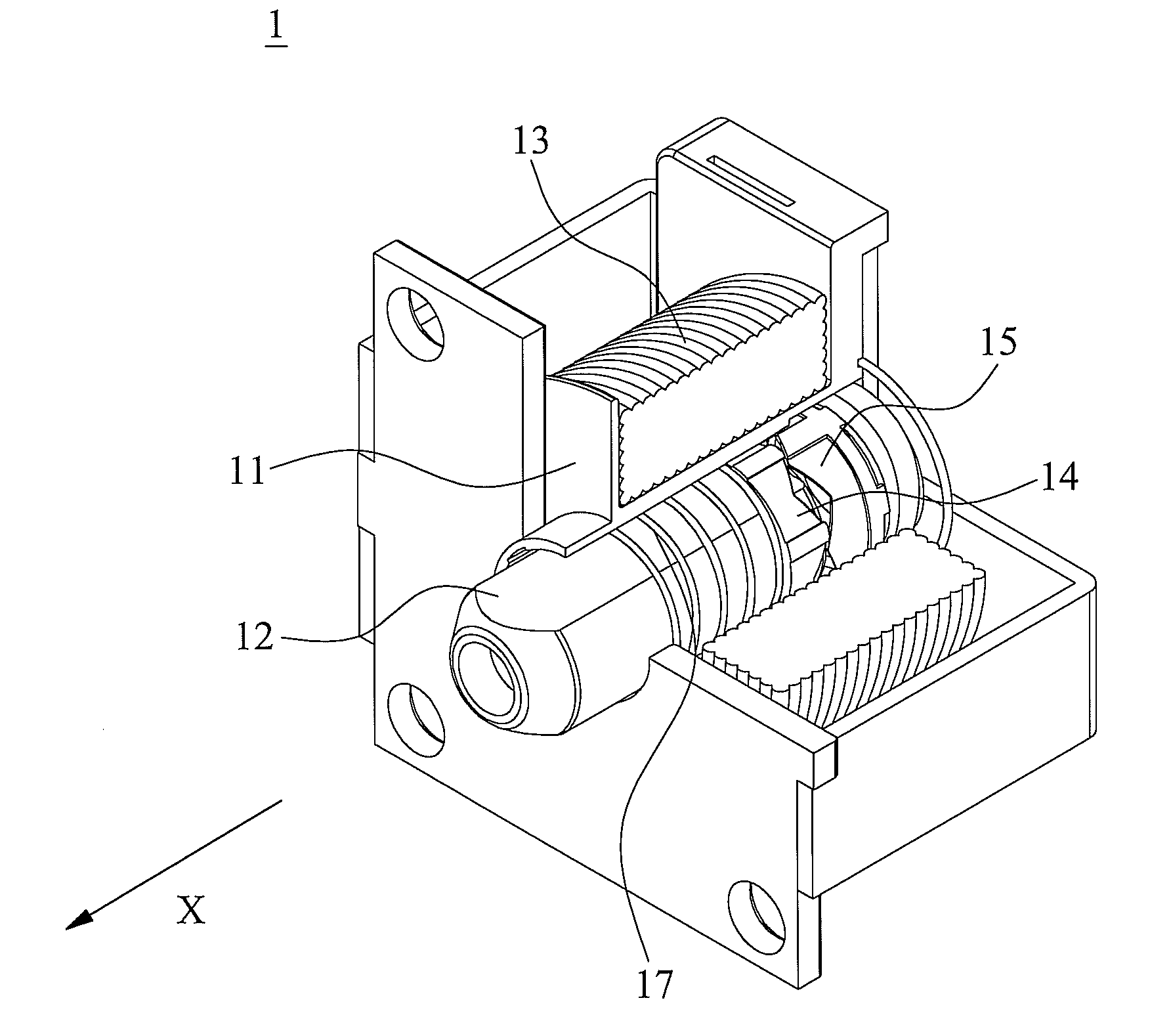
[0030]FIG. 3A is a stereogram of a solenoid valve with a part thereof removed in accordance with an embodiment of the present invention, and FIG. 3B is an exploded view of the solenoid valve of FIG. 3A. The solenoid valve 1 includes a bobbin 11, a valve rod 12, a coil 13, a slidable ring 14, a rotatable ring 15, a first spring 17, and a second spring 18.

[0031]The coil 13 is wound around the bobbin 11. The bobbin 11 has a through hole 111. The valve rod 12 is a movable iron core and disposed in the through hole 111 and is inwardly or outwardly movable in an axial direction X of the through hole 111 of the bobbin 11.

[0032]FIG. 4 is a stereogram of a bobbin with a part th...


PUM


Abstract

A solenoid valve comprises a bobbin, a coil, a valve rod, a slidable ring, and a rotatable ring. The bobbin has a through hole. The coil is wound around the bobbin. The valve rod is disposed in the through hole and is inwardly or outwardly movable along the through hole. The slidable ring is telescoped onto the valve rod and inwardly or outwardly movable with the valve rod. The rotatable ring is disposed inside the through hole and inside the slidable ring.

Description

CROSS REFERENCE TO RELATED APPLICATIONS[0001]This application claims priority of Taiwan Patent Application No. 097108997, filed on Mar. 14, 2008, the entirety of which is incorporated by reference herein.BACKGROUND OF THE INVENTION[0002]1. Field of the Invention[0003]The present invention relates to a solenoid valve, and in particular relates to a self-latch solenoid valve with a structural design that replaces a permanent magnet.[0004]2. Description of the Related Art[0005]A conventional self-latch solenoid valve is switched between an extended position and a retracted position by passing an electric current through a coil, wherein the position of the valve rod is fixed, even after the electric current is terminated. To save power, a conventional self-latch solenoid valve generally contains a magnet to attract and keep the valve rod in a retracted position when the electric current is terminated, thus, keeping the self-latch solenoid valve open.[0006]FIG. 1A is a stereogram of a co...

Claims


Application Information

Patent Timeline
Patent Type & Authority Applications(United States)
IPC IPC(8): F16K31/02
CPCF16K31/0675H01F7/1607H01F7/124
Inventor CHEN, CHIEH-CHENGTSAI, MING-CHIHLIN, CHIEN-CHIA
Owner DELTA ELECTRONICS INC
Why Eureka
Try Eureka