Heat exchanger for the feeding of fuel in internal combustion engines

a technology of heat exchanger and internal combustion engine, which is applied in the direction of engine cooling apparatus, stationary plate conduit assembly, fuel treatment, etc., can solve the problems of incorrect operation of engine components, loss of efficiency as thermal exchanging fluid, and energy lost in the transfer of heat from the engine to the radiator water, so as to reduce fuel consumption and environmental damage, simple, efficient and easy-to-install construction, the effect of double energy us

Inactive Publication Date: 2016-09-15
MAHLE METAL LEVE
View PDF0 Cites 4 Cited by
  • Summary
  • Abstract
  • Description
  • Claims
  • Application Information

AI Technical Summary

Benefits of technology

[0015]The invention therefore provides a triple heat exchanger, to be operatively associated with an automatic thermal management system for the feeding of fuel to an internal combustion engine under operation, allowing for a selective and sequential thermal exchange between the three fluids defined by the lubricant oil circulating inside the engine, by the cooling water circulating through a water radiator and inside the engine, and also by the fuel to be injected in the engine at a temperature suitable for the complete burning thereof inside the combustion chamber. With the thermal exchange between the fuel and the water in the first stage, followed by a second thermal exchange between the water circulated by the engine and the lubricant oil in the second stage, it is possible, by means of a simple, efficient and easily installed construction, to obtain the advantages of simultaneously cooling the lubricant oil and the radiator water, with double energetic use for heating the fuel to be supplied to the engine. The construction of the heat exchanger in two stages allow the latter to be mounted in a compact manner or even separately, for better adapting to the constructive features of the engine to which said heat exchanger will be applied. The proposed heat exchanger, when used together with an automatic thermal management system, allows that the heating of the fuel, either single or in a mixture, to be carried to the injection system of the engine in a better temperature condition for the combustion thereof, thereby reducing fuel consumption and damages to the environment, and improving the efficiency of the engine and also of the vehicle to which said engine is associated, the thermal energy used for the selective heating of the fuel being obtained from the very thermal energy dissipated by the internal combustion engine.

Problems solved by technology

However, the heat transferred from the engine to the radiator water represents an energy which is lost and even undesired, since if this heat remains stored in the water, it loses efficiency as a thermal exchanging fluid.
When overheated, the oil loses viscosity and may deteriorate, and consequently loses the desired lubricant properties and the capacity of cooling internal parts of the engine, impairing the correct operation of engine components, leading to major damages to the engine or even to the total loss of the vehicle engine.
However, the oil radiators presently in use do not exchange heat between the oil and the fuel.
Thus, as mentioned in said prior patent BR 10 2013 004382-6, in low temperature environments in which the fuel has the temperature thereof reduced to values at a distant low from the flash point temperature (“cold fuel”), there is a greater or lesser difficulty in burning the fuel fed to the engine, said difficulty being greater when using fuels having a high flash point.
Although the thermal exchange between the heat dissipated by the operating engine and the fuel is sufficient for, in principle, suitably heating a somewhat “cold” fuel, this is not a working condition that presents an optimized thermo-energetic condition, allowing for engine failures, jolts, slow acceleration response and even high emission of pollutants due to poor fuel burning.

Method used


Image

  • Heat exchanger for the feeding of fuel in internal combustion engines
  • Heat exchanger for the feeding of fuel in internal combustion engines
  • Heat exchanger for the feeding of fuel in internal combustion engines

Examples


Embodiment Construction

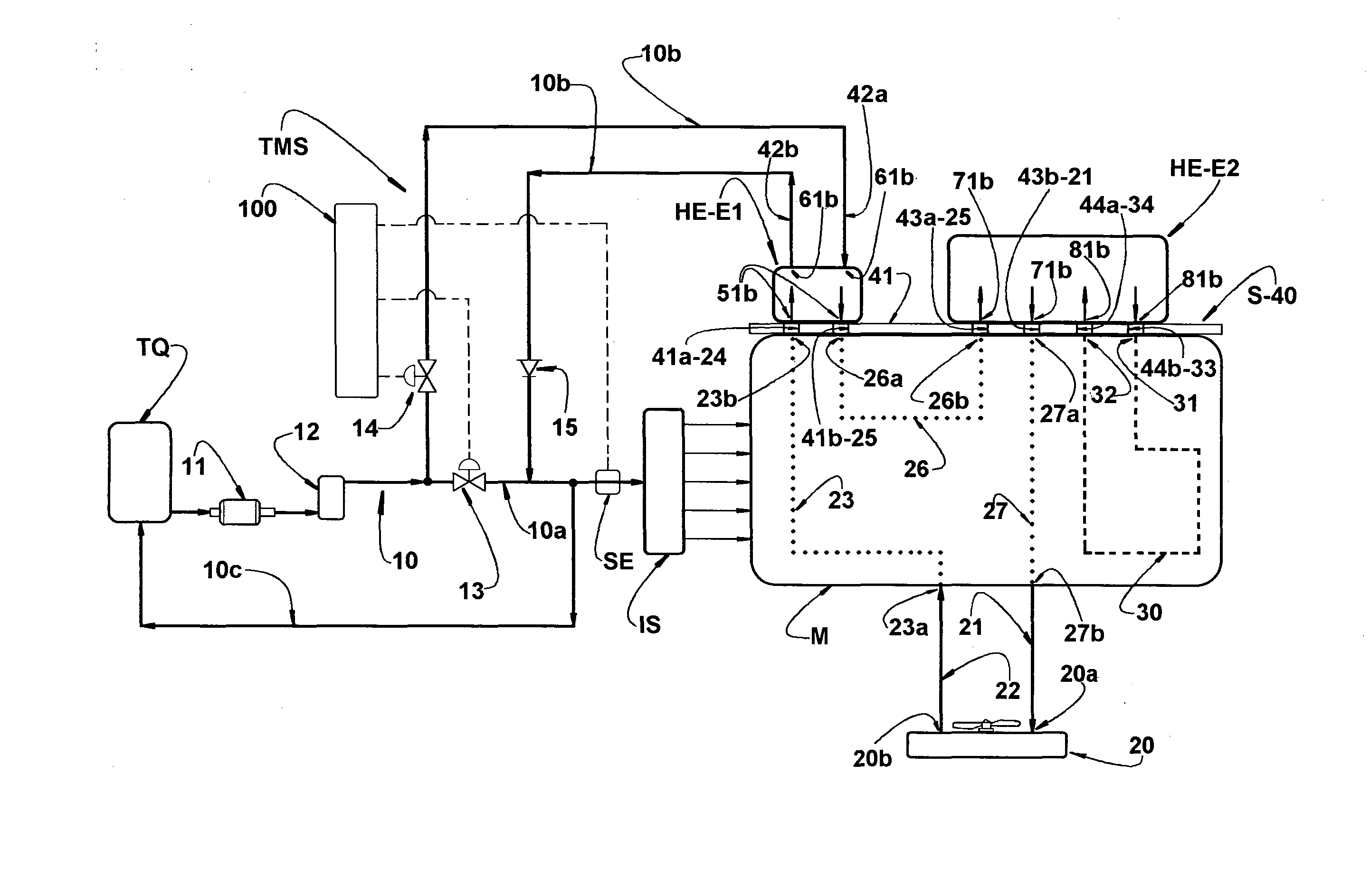
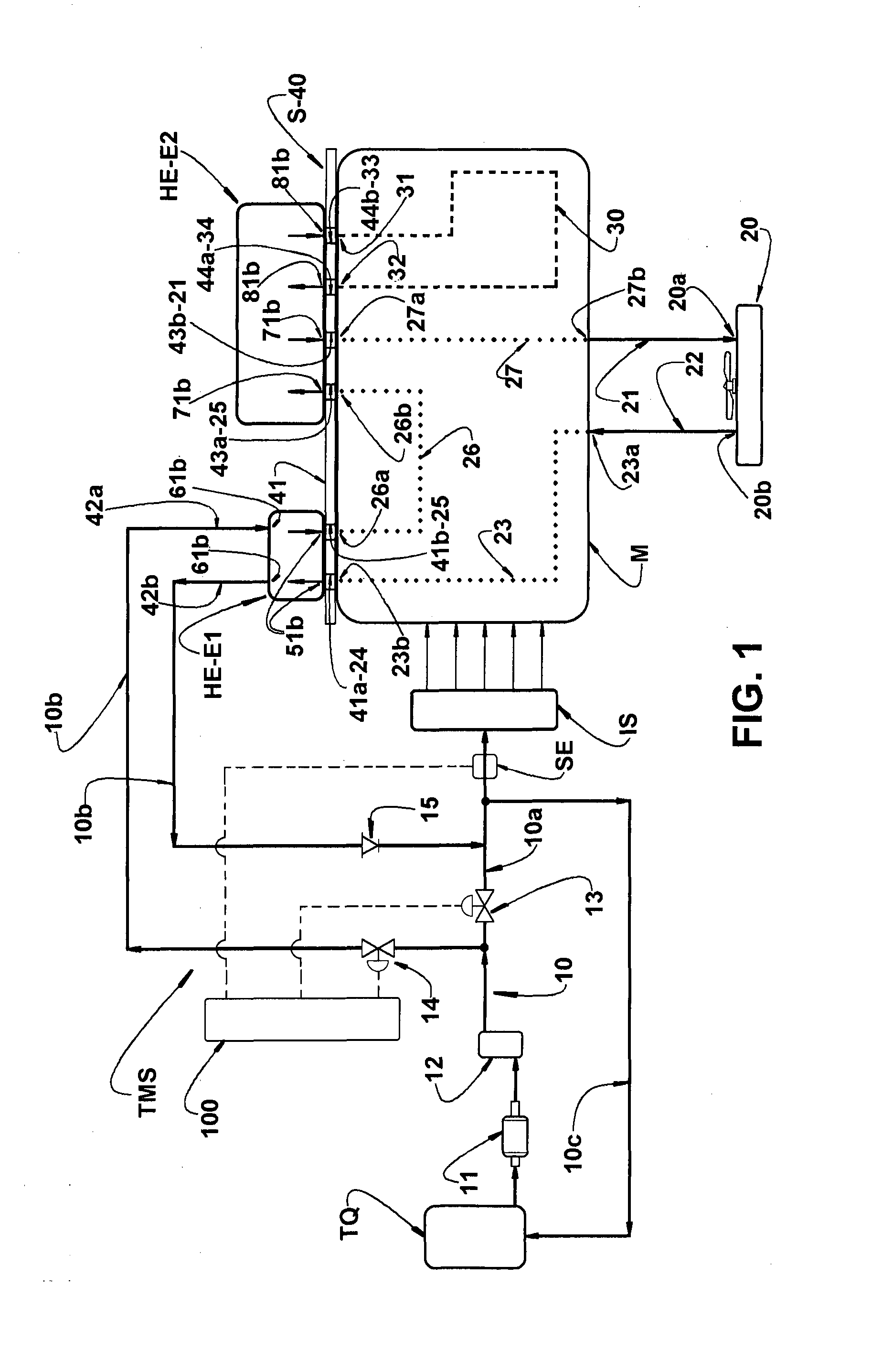
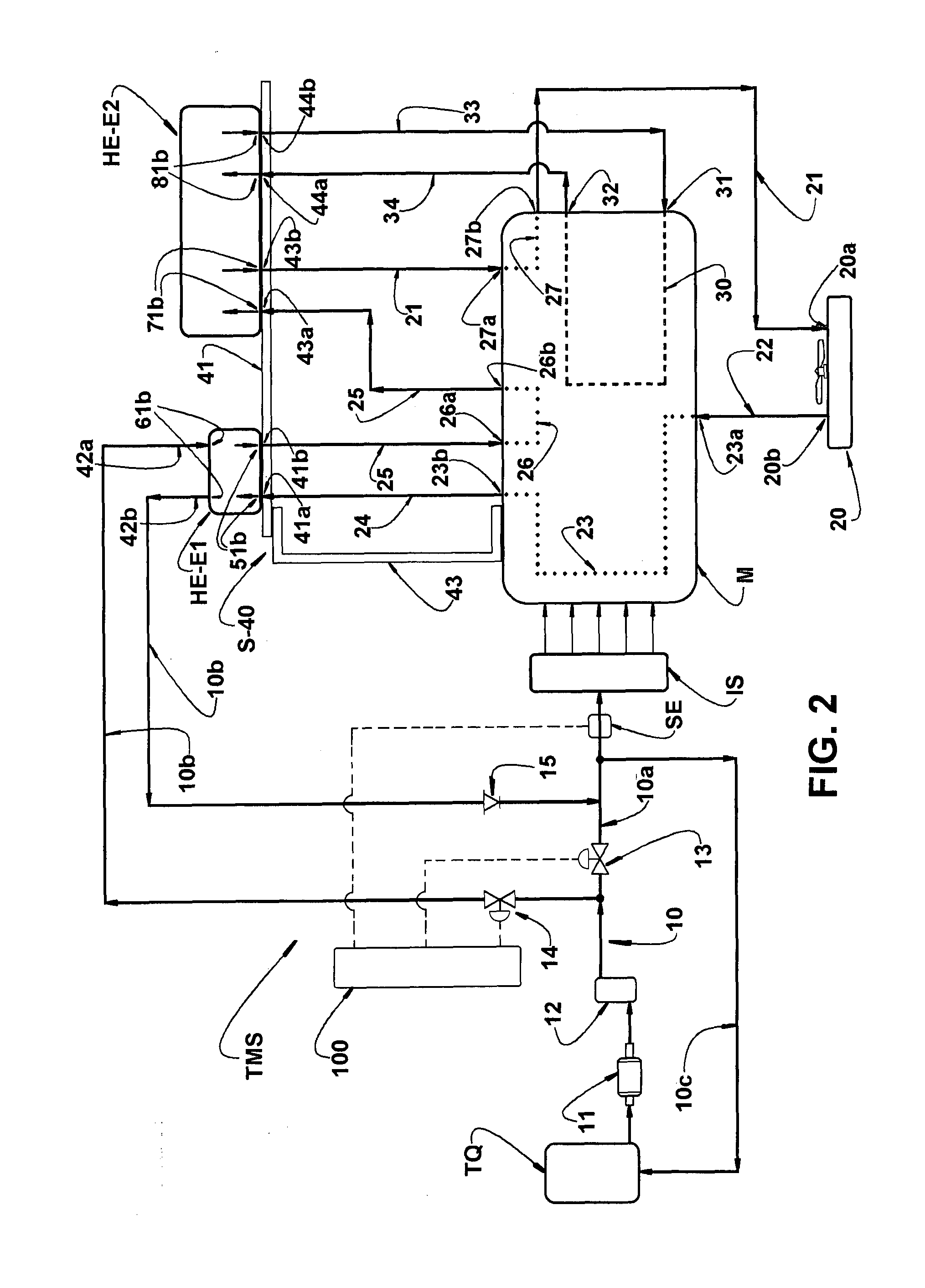
[0023]As mentioned above and illustrated in the attached drawings, the heat exchanger HE of the invention is applied to an internal combustion engine M, using a single fuel or a varying mixture of fuels presenting different vaporization temperatures, as is the case of “flex” engines which use, for example, gasoline, ethanol or a mixture thereof in different proportions. The heat exchanger HE of the invention was developed to operate together with a thermal management system TMS for the feeding of fuel during the entire vehicle operation, in order to maintain the fuel being supplied to the engine M at an optimized temperature for efficient combustion, lower than that of the vaporization point. The thermal management system TMS may be defined, for example, as described in prior patent application BR10 2013 004382-6, of the same applicant.

[0024]In FIGS. 1 and 2 of the attached drawings are illustrated two possible assembly embodiments of the heat exchanger HE, in a thermal management s...


PUM


Abstract

The heat exchanger comprises a first and a second stage (E1,E2), each having an inlet and an outlet of water, the second stage (E2) having an inlet and an outlet of oil, the first stage (E1) being provided with fuel inlet and outlet nozzles, selectively connected, in parallel, to the fuel supply to the engine (M). The inlet and outlet of water of the first stage (E1) are respectively connected to the outlet of the water radiator, by means of a cooling water circuit internal to the engine (M), and to the water inlet of the second stage (E2). The water outlet of the second stage (E2) is connected to the inlet of a water radiator, and the inlet and outlet of oil in the second stage (E2) are connected in series to a lubricant oil circuit internal to the engine (M).

Description

FIELD OF THE INVENTION[0001]The present invention refers to a heat exchanger, for example, of the plate type, developed to allow a sequential triple thermal interaction between the fuel to be injected in an internal combustion engine in normal operation, and the two cooling fluids defined by the lubricant oil and water, for allowing the fuel to be selectively and suitably heated under control of a thermal management system for feeding the engine with different fuels, each presenting a respective and particular flash point or vaporization point.BACKGROUND OF THE INVENTION[0002]As described in patent application BR 10 2013 004382-6, of the same assignee, improvements in energy efficiency, handling and reduction in the emission of pollutants may be achieved by means of a thermal management system for the feeding of fuel in an internal combustion engine, which is able to maintain the fuel at a temperature more adequate to the combustion upon its feeding to the engine. The thermal manage...

Claims


Application Information

Patent Timeline
Patent Type & Authority Applications(United States)
IPC IPC(8): F02M31/10F28D9/00F01M5/00
CPCF02M31/10F28D9/0093F01M5/002F01P11/08F02M31/102F02M31/14F28D9/0037F28D9/005F28D2021/0087F28D2021/0089F28F2009/004Y02T10/12
Inventor AZEVEDO JUNIOR, EDSON VALDOMIRO DEAMARAL, TADEU MIGUEL MALAGO
Owner MAHLE METAL LEVE
Why Eureka
Try Eureka