Control device for hybrid vehicle

a control device and hybrid technology, applied in the direction of machines/engines, vehicle sub-unit features, engine starters, etc., can solve the problems of reducing the efficiency of the use of engine energy, and achieve the effect of accurate determination, reducing the consumption of electric energy, and increasing the rotation speed of the engin

Active Publication Date: 2015-10-13
TOYOTA JIDOSHA KK
View PDF28 Cites 4 Cited by
  • Summary
  • Abstract
  • Description
  • Claims
  • Application Information

AI Technical Summary

Benefits of technology

[0009]According to the foregoing configuration, since the engine starter and the MG are jointly used to start the engine upon starting the engine with the engine starter, the assist torque generated by the MG when the engine is started with the engine starter can be attained at an appropriate timing; that is, at the time that the engine speed starts to increase. Accordingly, since the engine speed that was once increased during the start of the engine will not decrease, the energy that was consumed for starting the engine can be used efficiently.
[0010]Here, preferably, with the clutch mechanism being engaged, the engine is started with the MG before rotation speed of the engine, which has been increased by the engine starter, decreases. According to the foregoing configuration, the energy that was used for increasing the engine speed can be efficiently used.
[0011]Moreover, preferably, an engagement command for engaging the clutch mechanism is sent before sending a start command for starting the engine upon starting the engine with the engine starter. According to the foregoing configuration, since an engagement command for engaging the clutch mechanism is sent before sending a start command for starting the engine, the clutch mechanism can be engaged at the time that the engine speed starts to increase, and the assist torque by the clutch mechanism can thereby be attained at an appropriate timing. Accordingly, since the engine speed that was once increased during the start of the engine will not decrease, the energy that was consumed for starting the engine can be used efficiently.
[0013]Moreover, preferably, the preceding sending time or the start response time is determined based on at least one among the actual temperature of engine coolant, stop phase position of the engine and presence of reverse flow of exhaust gas when the engine is stopped, according to a pre-stored relation. Moreover, the preceding sending time or the clutch response time is determined based on at least one of the actual clutch ambient temperature and differential rotation speed of the clutch, according to a pre-stored relation. According to the foregoing configuration, there is an advantage in that the preceding sending time can be accurately determined.
[0014]Moreover, preferably, the engine is started by so-called ignition start of injecting and igniting fuel in a cylinder in an expansion stroke among a plurality of cylinders provided to the engine, generating torque from an explosion in the cylinder, and repeating this processing to increase the rotation speed of the engine. According to the foregoing configuration, in a hybrid vehicle equipped with the clutch mechanism, electric energy for increasing the rotation speed of the engine is not required, or consumption of electric energy can be reduced in comparison to the case of engaging the clutch mechanism from the start to attain the assist torque generated by the MG.

Problems solved by technology

Particularly, in cases where it is relatively difficult to increase the engine speed upon starting the engine such as when the engine is started at a low temperature or the engine is started by ignition start of injecting and igniting fuel in a cylinder in an expansion stroke to increase the engine speed from the explosion energy generated in that cylinder, and the response lag of the clutch mechanism increases, since the assist for maintaining the once-increased engine speed and further increasing such engine speed will be delayed before the clutch mechanism is in its engaged state, there were cases where the once-increased engine speed would decrease, thereby disabling the efficient use of the energy that was consumed for starting the engine.

Method used


Image

  • Control device for hybrid vehicle
  • Control device for hybrid vehicle
  • Control device for hybrid vehicle

Examples


Embodiment Construction

[0026]The preferred embodiments of this invention are now explained in detail with reference to the drawings.

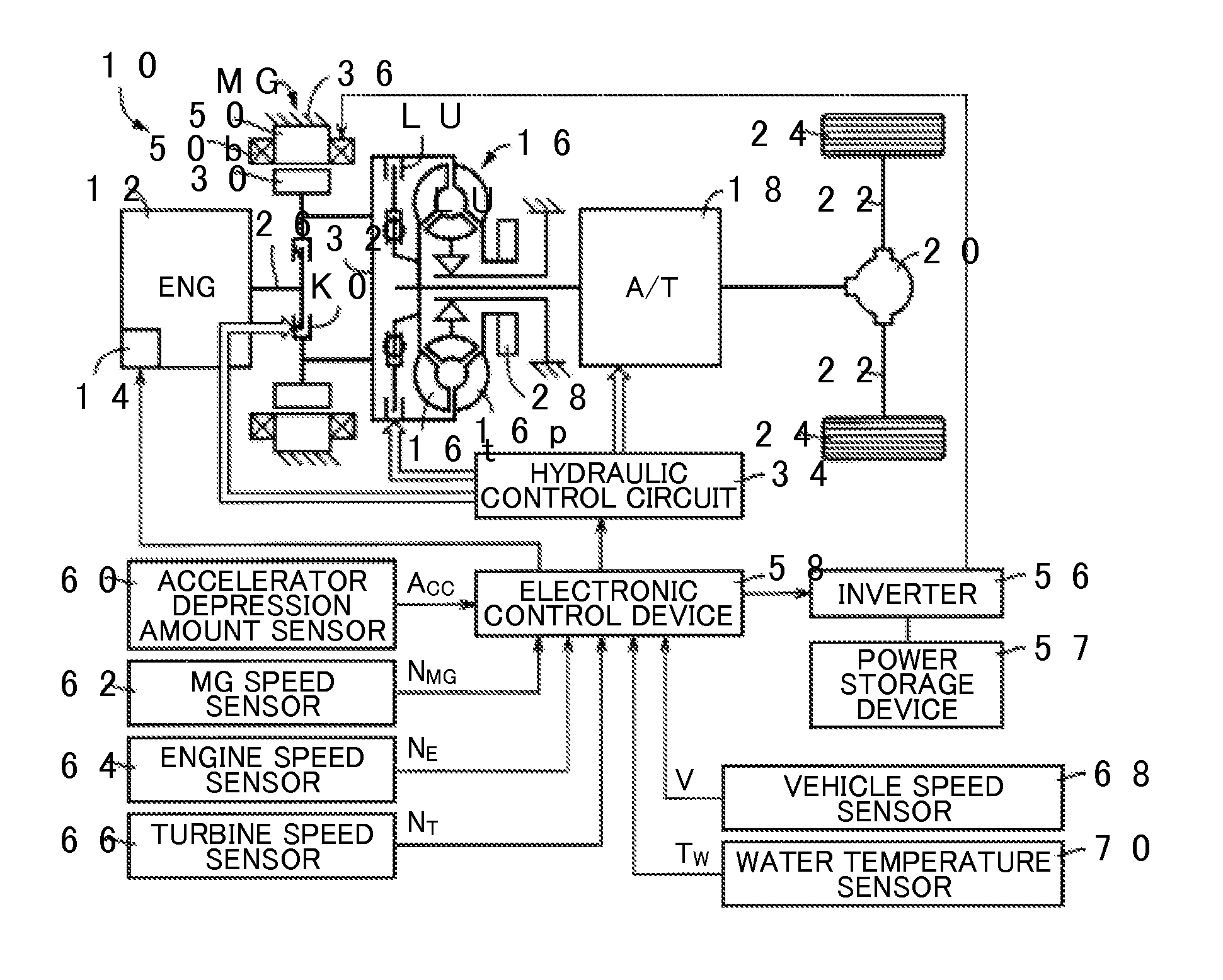
[0027]FIG. 1 is a diagram conceptually showing the configuration of a drive system of the drive device 10 for a hybrid vehicle as one embodiment of this invention. The drive device 10 shown in FIG. 1 includes an engine 12 and a MG that function as drive sources, and the driving force that is generated by the engine 12 and the MG is transmitted to a pair of left and right driving wheels 24 via a torque converter 16, an automatic transmission 18, a differential gear unit 20, and a pair of left and right axles 22, respectively. Based on this kind of configuration, the drive device 10 is driven by at least one of the engine 12 and the MG as the operational drive source. In other words, the drive device 10 selectively executes one among an engine operation which exclusively uses the engine 12 as the operational drive source, an EV operation (motor operation) which exclusively uses...


PUM


Abstract

Provided is a control device for a hybrid vehicle capable of attaining an assist torque generated by a clutch mechanism at an appropriate timing, upon starting the engine. Since an electronic control device outputs an engagement command for engaging a clutch (clutch mechanism) at a time preceding an (ignition) start command time for igniting an engine by a preceding-sending time, the clutch becomes engaged when the engine speed starts to increase, and the assist torque generated by the clutch mechanism can thus be obtained at an appropriate timing. Because the engine speed that was once increased upon starting the engine is not decreased, the energy that was consumed for starting the engine can be effectively used.

Description

CROSS REFERENCE TO RELATED APPLICATION[0001]This is a national phase application based on the PCT International Patent Application No. PCT / JP2011 / 070295 filed on Sep. 6, 2011, the entire contents of which are incorporated herein by reference.TECHNICAL FIELD[0002]This invention relates to a control device, for a hybrid vehicle provided with a clutch on a power transmission path between an engine and a motor generator (MG), and particularly relates to technology for improving the fuel efficiency by expanding the MG operation range of the hybrid vehicle that is operated with its MG as the driving power source.BACKGROUND ART[0003]As one type of hybrid vehicles, there is a drive device for a hybrid vehicle provided with a clutch on a power transmission path between an engine and a MG. This hybrid vehicle can selectively use at least one of the engine and the MG as its operational drive source. Generally speaking, a MG operation which disengages the engine by releasing the clutch mechanis...

Claims


Application Information

Patent Timeline
Patent Type & Authority Patents(United States)
IPC IPC(8): B60W20/00B60W10/02B60K6/547B60K6/48B60W10/06B60W10/08F02D29/02B60L50/16
CPCB60W20/40B60W10/08B60W20/108B60K6/48B60K6/547B60W10/02B60W10/06B60Y2400/426F02D29/02Y02T10/6221Y02T10/6286Y10S903/93Y02T10/62B60W2510/0241B60W2510/0291B60W2510/0676B60W2510/0685F02N11/006F02N11/04F02N11/0851F02N99/006F02N2200/022F02N2300/2011F02P5/1506
Inventor IDESHIO, YUKIHIKOKOJIMA, SUSUMUNAKANISHI, NAOKISATO, AKIHIRO
Owner TOYOTA JIDOSHA KK
Why Eureka
Try Eureka