Gap inspection apparatus

a technology of gap inspection and gimbal, which is applied in the direction of dynamo-electric components, structural/machine measurement, instruments, etc., can solve the problems of limited space and frequent availability of narrow accesses, and achieve the effect of convenient transportation and handling and versatile manner

Active Publication Date: 2009-10-15
GENERAL ELECTRIC TECH GMBH
View PDF4 Cites 12 Cited by
  • Summary
  • Abstract
  • Description
  • Claims
  • Application Information

AI Technical Summary

Benefits of technology

[0035]In a further embodiment, the sensor platform has a pivotable mirror, for example in conjunction with the camera. This is moved to a suitable position corresponding to the distance between the surface to be inspected and the sensor platform. Furthermore, the pivotable mirror ensures visual inspection of a surface from different viewing angles.
[0036]In a further embodiment of the invention, the sensor platform has one or more instruments in order to grip and transport objects in the gap. This makes it possible to simultaneously remove any foreign bodies or undesirable material.
[0037]As a result of the arrangement of the mount and the sensor platform, as well as the nature of the controlled movement of the sensor platform in the gap, apparatus according to the invention allows measurements in gaps for example with a height from 4 mm. Furthermore as a result of the small and light weight construction, the apparatus can be transported and handled easily, and can therefore be used in a versatile manner.

Problems solved by technology

However, only a limited amount of space and narrow accesses are frequently available for inspection.

Method used


Image

  • Gap inspection apparatus
  • Gap inspection apparatus
  • Gap inspection apparatus

Examples


Embodiment Construction

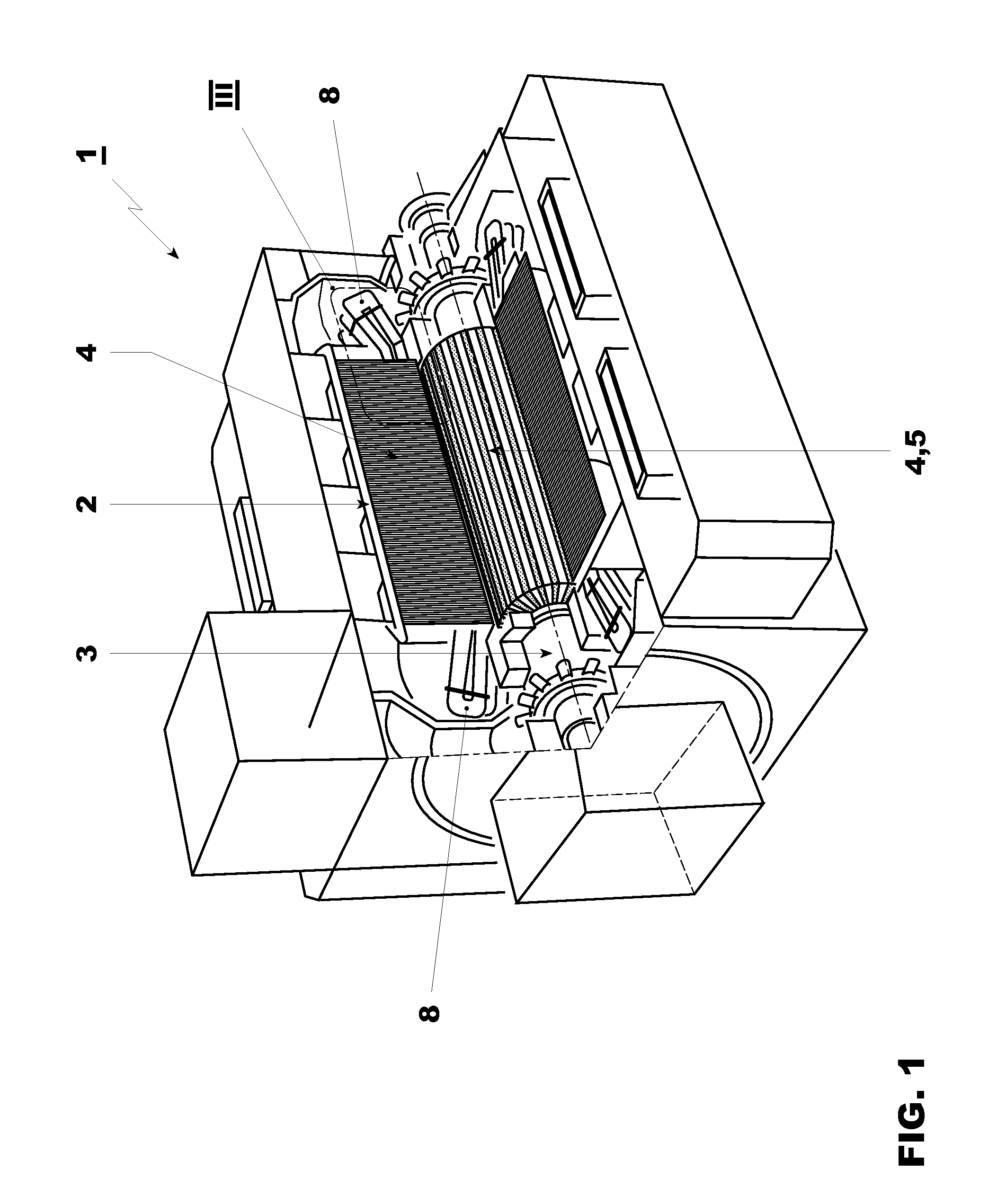
[0054]FIG. 1 shows a general view of a generator 1 in a power station, in particular of its stator 2 and rotor 3, each with ferromagnetic elements 4 (white) and non-ferromagnetic elements 5 (shaded grey).

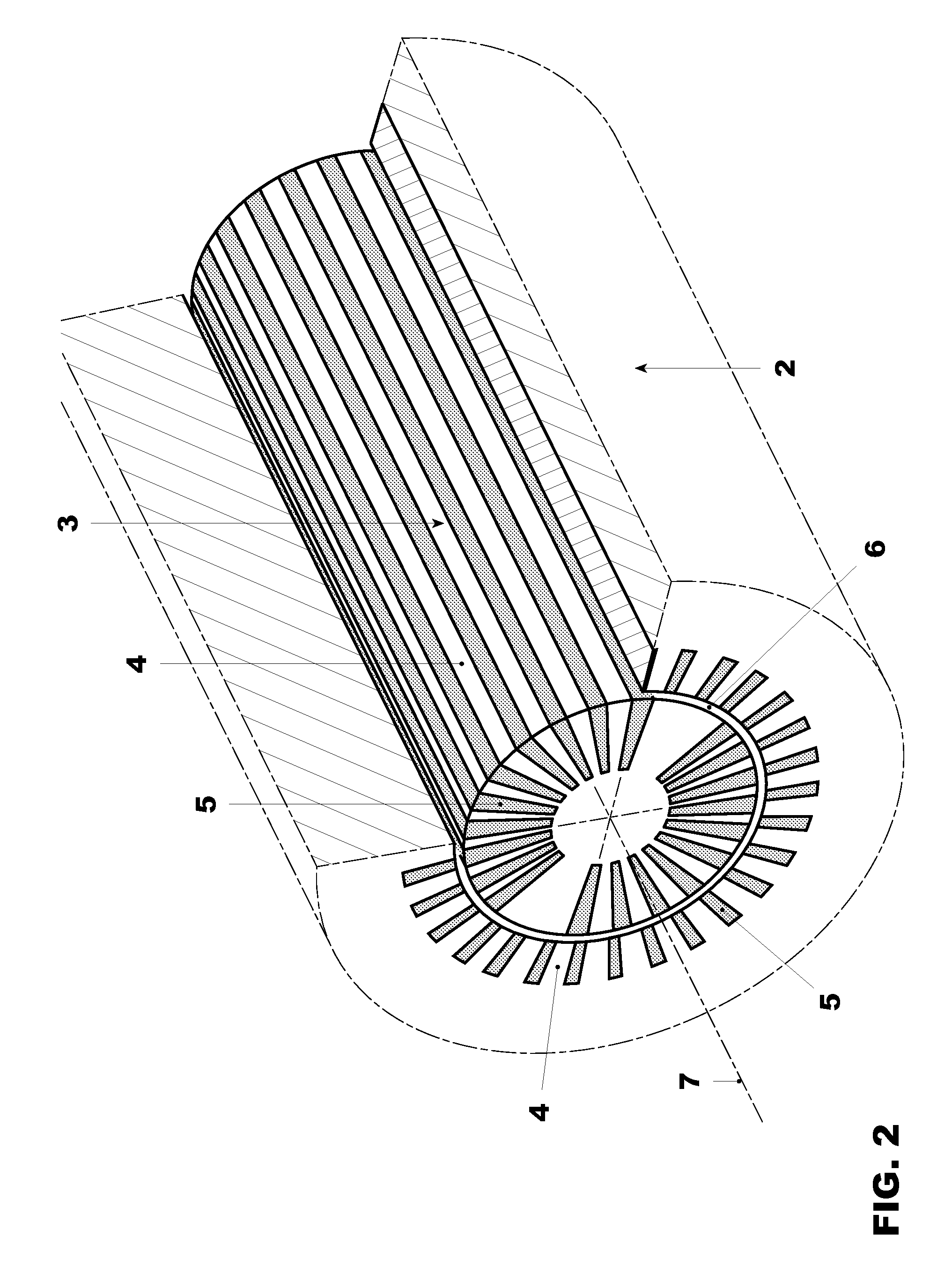
[0055]FIG. 2 shows a more detailed view of the stator 2 and rotor 3 between which a narrow, annular air gap 6 extends. The surfaces of the stator and rotor each have ferromagnetic elements 4 and non-ferromagnetic elements 5, which are arranged alternately over the circumference and extend parallel to the generator axis 7. The width of the individual elements on the stator is generally constant over its circumference. The width is likewise constant on the rotor, with the exception of the area of the magnetic poles. On the rotor, the ferromagnetic material is the rotor material itself. A plurality of slots extend parallel to the rotor axis, in which slots the winding is arranged and is secured in the slots by wedges. These wedges and the winding form the non-ferromagnetic elements. Th...


PUM


Abstract

An apparatus for inspection of a gap between two surfaces, at least one of which is ferromagnetic, for example in a generator, includes a sensor platform (26) for one or more sensors (26a) and an elongated mount (23), which can be moved out, for the sensor platform (26). The mount (23) can be moved in and out of the gap through an access opening, can be moved out over the length of the gap and can be rolled up outside the gap by a drive (24). In its moved-out state, the mount (23) has a curvature in a lateral cross section. In addition, the mount (23) has a plurality of magnets (27) by which the mount (23) is brought into contact with a ferromagnetic surface. The magnets (27) are attached to the side of the mount (23) facing away from the ferromagnetic surface, ensuring that the mount (23) slides along a ferromagnetic surface. The apparatus allows inspection of gaps from a height of 4 mm and is distinguished by a simple and physically small design.

Description

[0001]This application claims priority under 35 U.S.C. §119 to European application number 08 154 462.9, filed 14 Apr. 2008, the entirety of which is incorporated by reference herein.BACKGROUND[0002]1. Field of Endeavor[0003]The invention relates to an apparatus for inspection of a narrow air gap between two surfaces with a probe, wherein at least one of the two surfaces is ferromagnetic. The invention relates in particular to an apparatus having a motor for movement of the probe, wherein the motor is arranged outside the gap and the probe can be moved into the gap through a single access.[0004]2. Brief Description of the Related Art[0005]Machines, motors and industrial apparatuses with a long operating life are typically inspected for their serviceability at regular time intervals. For example, turbines, boilers or generators are inspected for damage on the surfaces of the components, in order to prevent failure or damage during operation, in that any damage must be rectified or co...

Claims


Application Information

Patent Timeline
Patent Type & Authority Applications(United States)
IPC IPC(8): G01R31/34G01M99/00
CPCH02K11/001G01R31/34H02K11/20
Inventor MOSER, ROLANDHUGI, NIKLAUSMARK, BERNHARDISLER, PHILIPPHONOLD, SIMONERNI, JOSEF
Owner GENERAL ELECTRIC TECH GMBH
Why Eureka
Try Eureka