Filtration of fluids using conformable porous shape memory media

a technology of conformable porous shape and fluid, applied in the direction of filtration separation, separation process, borehole/well accessories, etc., can solve the problems affecting the performance of sand control devices

Pending Publication Date: 2022-01-06
BAKER HUGHES OILFIELD OPERATIONS LLC
View PDF4 Cites 0 Cited by
  • Summary
  • Abstract
  • Description
  • Claims
  • Application Information

AI Technical Summary

Benefits of technology

[0002]An embodiment of a fluid control device includes a support structure configured to be deployed in a borehole, and a filtration component disposed at the support structure, the filtration component including a porous medium made from a thermoplastic polymer material, the porous medium including an open cell foam. The porous medium has a porosity selected to cause the porous medium to exhibit shape memory behavior, and the porous medium is configured to be compacted from an initial shape to a compacted shape, deployed in the borehole, and subsequently expanded due to a downhole temperature to conform to a surface of the borehole.
[0003]An embodiment of a fluid control method includes deploying a fluid control device in a borehole, the fluid control device including a support structure and a filtration component disposed at the support structure, the filtration component including a porous medium made from a thermoplastic polymer material, the porous medium including an open cell foam. The porous medium has a porosity selected to cause the porous medium to exhibit shape memory behavior, where the fluid control device is deployed when the porous medium is in a compacted shape. The method also includes activating the porous medium to cause the porous medium to expand due to a downhole temperature, and conform to a surface of the borehole, and flowing a fluid through the porous medium and filtering undesirable material from the fluid.

Problems solved by technology

In some cases, high temperature conditions experienced downhole can affect the performance such sand control devices.

Method used


Image

  • Filtration of fluids using conformable porous shape memory media
  • Filtration of fluids using conformable porous shape memory media
  • Filtration of fluids using conformable porous shape memory media

Examples


embodiment 1

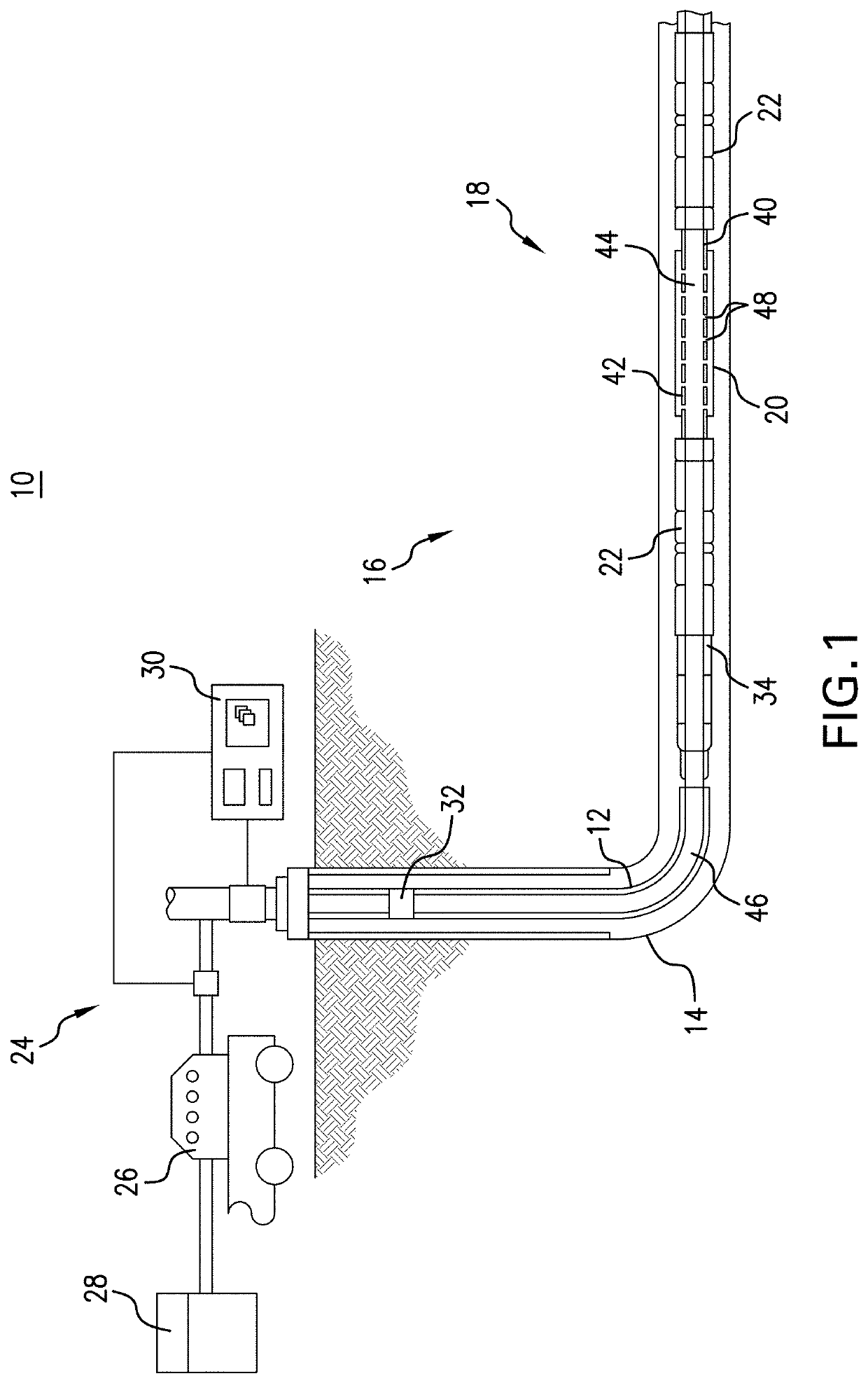
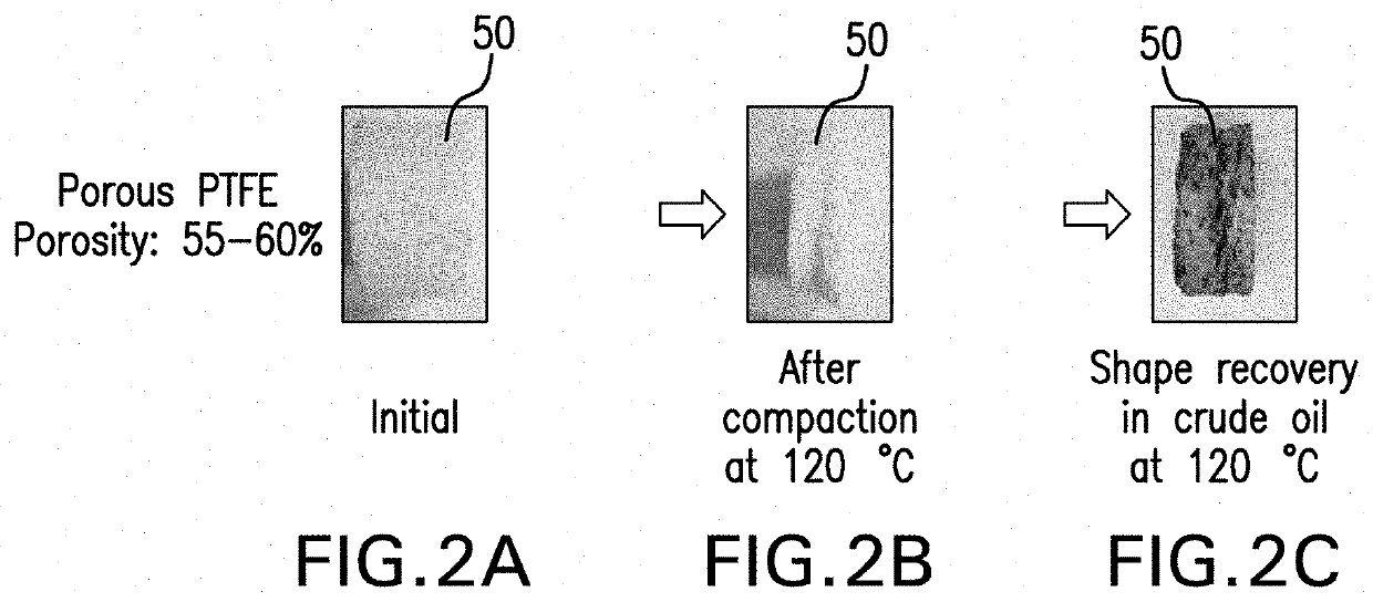
[0045] A fluid control device comprising: a support structure configured to be deployed in a borehole; a filtration component disposed at the support structure, the filtration component including a porous medium made from a thermoplastic polymer material, the porous medium including an open cell foam, the porous medium having a porosity selected to cause the porous medium to exhibit shape memory behavior, the porous medium configured to be compacted from an initial shape to a compacted shape, deployed in the borehole, and subsequently expanded due to a downhole temperature to conform to a surface of the borehole.

embodiment 2

[0046] The device of any prior embodiment, wherein the fluid control device is configured as a screen assembly, the screen assembly configured to filter undesirable material including sand from fluid entering the borehole from a subterranean region, the support structure including a tubular having a fluid conduit defined therein, the porous medium being at least one layer disposed on an outer surface of the tubular and at least partially surrounding the tubular.

embodiment 3

[0047] The device of any prior embodiment, wherein the porous medium is configured to have a glass transition temperature that is greater than a subterranean temperature.


PUM

PropertyMeasurementUnit
porosityaaaaaaaaaa
porosityaaaaaaaaaa
porosityaaaaaaaaaa

Abstract

A fluid control device includes a support structure configured to be deployed in a borehole, and a filtration component disposed at the support structure, the filtration component including a porous medium made from a thermoplastic polymer material, the porous medium including an open cell foam. The porous medium has a porosity selected to cause the porous medium to exhibit shape memory behavior, and the porous medium is configured to be compacted from an initial shape to a compacted shape, deployed in the borehole, and subsequently expanded due to a downhole temperature to conform to a surface of the borehole.

Description

BACKGROUND[0001]Various tools are utilized in subterranean operations, such as hydrocarbon exploration, drilling and completion operations, to increase or maximize production efficiency. Sand control devices such as sand screens are utilized to control the ingress of particulate contaminants into production fluid and to aid in stabilizing production formations. Examples of sand control devices include screen assemblies having conformable sleeves or components that are expanded downhole. In some cases, high temperature conditions experienced downhole can affect the performance such sand control devices.BRIEF DESCRIPTION OF THE INVENTION[0002]An embodiment of a fluid control device includes a support structure configured to be deployed in a borehole, and a filtration component disposed at the support structure, the filtration component including a porous medium made from a thermoplastic polymer material, the porous medium including an open cell foam. The porous medium has a porosity s...

Claims


Application Information

Patent Timeline
Patent Type & Authority Applications(United States)
IPC IPC(8): E21B43/08B01D39/12B01D39/16B01D35/02
CPCE21B43/082B01D39/12B01D39/1676B01D2239/1208B01D2201/04B01D2239/0291B01D35/02B01D2239/0428B01D39/083B01D39/086B01D2239/0258B01D2239/0407
Inventor SADANA, ANILAGRAWAL, DEVESH
Owner BAKER HUGHES OILFIELD OPERATIONS LLC
Why Eureka
Try Eureka