
Reaction chamber with removable liner

a technology of reaction chamber and liner, which is applied in the direction of chemical vapor deposition coating, coating, metal material coating process, etc., can solve the problems of substrate coating failure, unusable use, reactant byproduct contamination of reaction chamber such as gas deposition chamber, etc., and achieve the effect of reducing the volume of gas

Inactive Publication Date: 2016-01-07
ULTRATECH INT INC
View PDF3 Cites 1 Cited by
  • Summary
  • Abstract
  • Description
  • Claims
  • Application Information

AI Technical Summary

Benefits of technology

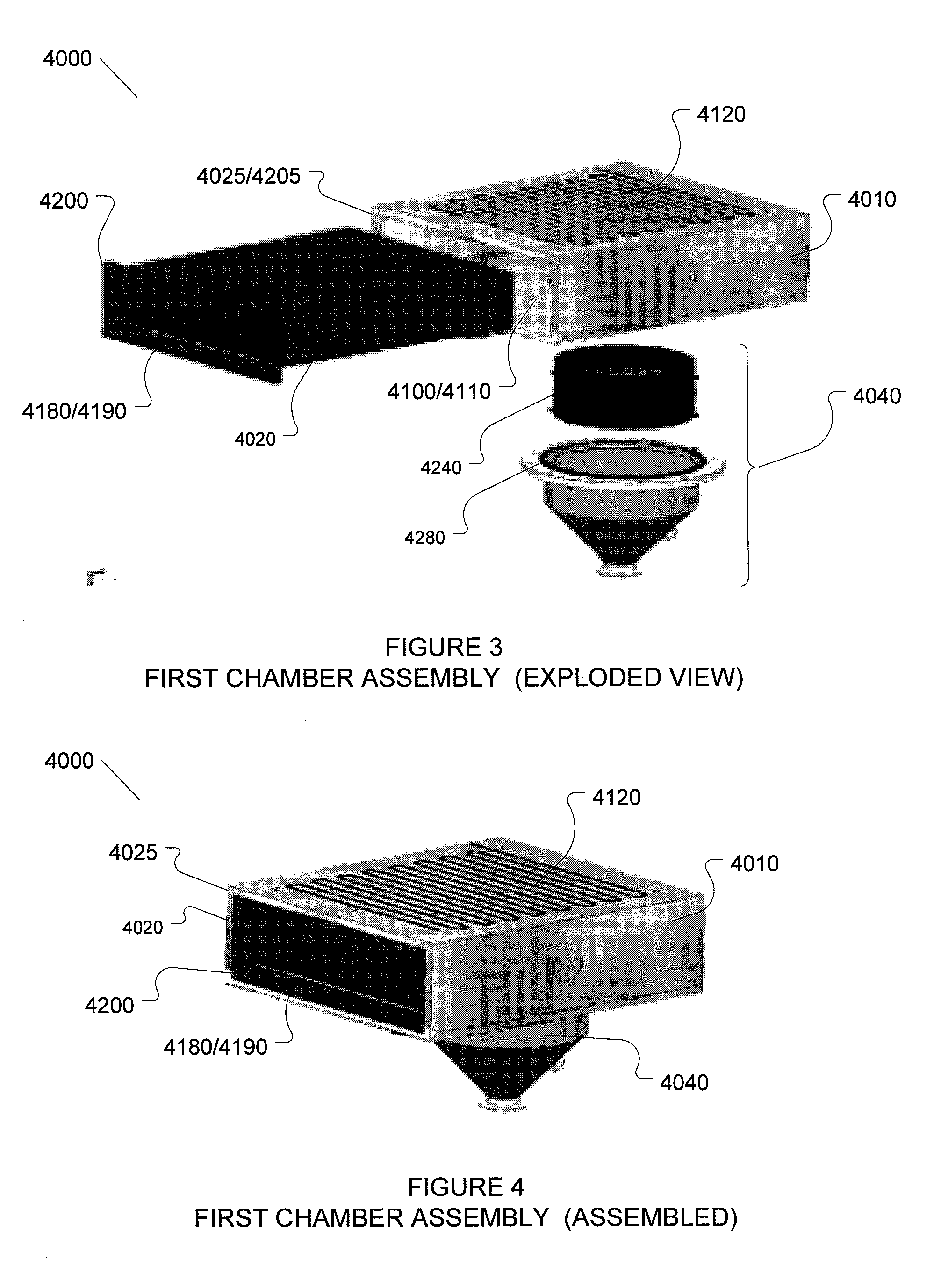
This patent describes a reaction chamber assembly for coating substrates. The assembly includes an outer wall made of metal or ceramics that encloses the entire chamber and is heated by heaters. The assembly also has an exit plenum for drawing gas out of the chamber. The exit plenum has a volume that allows gas to be drawn into it over the entire length of the chamber and is designed to remove undesirable materials from the gas. The patent also notes that the input and output plenums are made of stainless steel and can be cleaned mechanically. The technical effect of this invention is to provide a reliable and efficient tool for coating substrates in a controlled atmosphere.

Problems solved by technology

Reaction chambers such as gas deposition chambers can become contaminated with reactants and or reactant byproducts.
This may occur over prolonged use wherein reactants introduced into the reaction chamber react with internal walls thereof and with other elements inside the reaction chamber and build up extensive coating layers or contaminants on the internal walls and the other elements, rendering them unusable.
Over time, contaminant build up on the internal walls may begin to crack and peel causing substrate coating failures.
Other failures due to contaminant build up include sensor failure, reduced wall and substrate temperatures, or increases in thermal cycling times and concerns for human safety.
While such cleaning occurrences are predictable and can be planned for, they nonetheless disrupt production cycles.
Unscheduled cleaning or maintenance events may occur when a deposition chamber becomes accidently contaminated by a hazardous material and needs to be decontaminated immediately for human safety reasons.
In these cases, the cleaning or decontamination is unexpected and may be very disruptive to a production cycle.
However, the ex situ method is undesirable because of the excessive time required to disassemble, clean and reassemble the chamber.
However the in situ cleaning method is undesirable because the etch rate is slow, because the etching gas is corrosive and otherwise hazardous, e.g. a hazard to human safety, and because the etching gas may remain in the chamber and contaminate future substrate coating cycles.
However, beyond recommending materials for the liner, Cook et al. does not disclose a liner structure of any kind and is completely silent about how the reactants can be contained within the one or more removable liners covering the chamber walls in order prevent the chamber walls from becoming contaminated.
An effective liner needs to contain reactants therein in order to prevent the reactants from contaminating the chamber walls and this containment is made more difficult without the benefit of a high pressure gradient across the liner wall.

Method used


Image

  • Reaction chamber with removable liner
  • Reaction chamber with removable liner
  • Reaction chamber with removable liner

Examples


first embodiment

ALD System First Embodiment

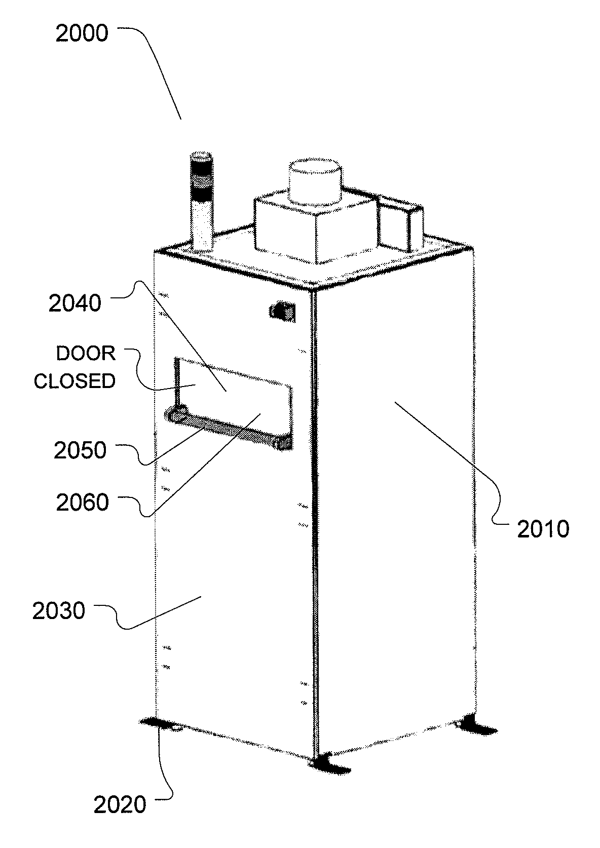
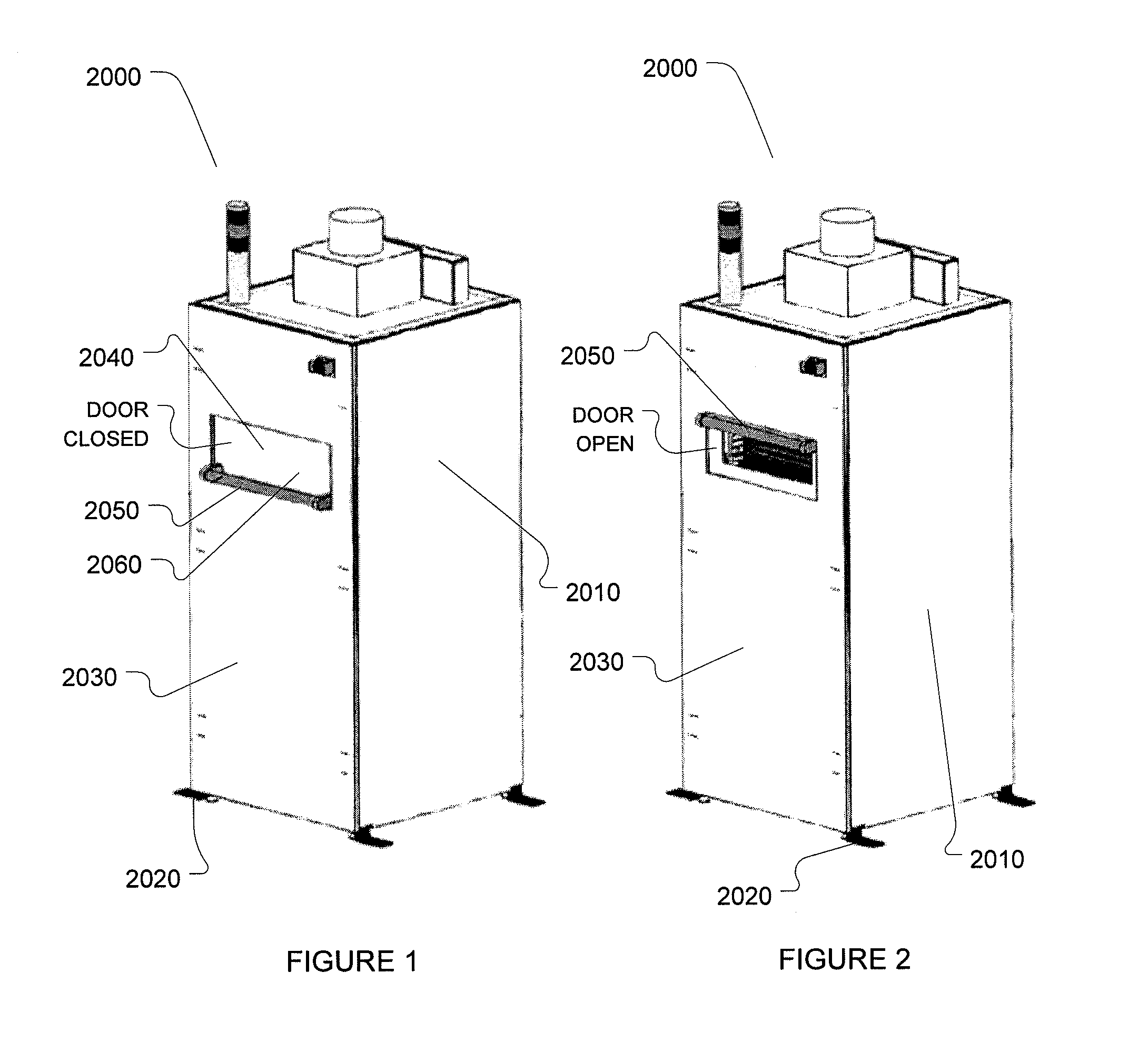
[0042]Referring to FIGS. 1 and 2, an exemplary first embodiment of an atomic layer deposition system (ALD) (2000) configured according to the present invention is constructed with a floor standing system cabinet (2010) supported on four feet (2020) having a front face (2030) that includes an access door assembly (2040). The access door assembly (2040) includes a door handle (2050) mounted on an outer door panel (2060). Both the outer door panel (2060) and the door handle are thermally insulated to protect an operator when handling the door handle (2050). The access door assembly (2040) is shown in a closed or operating position in FIG. 1 and in an open or loading / unloading position in FIG. 2. The access door assembly (2040) provides access through the system cabinet (2010) to a gas deposition or reaction chamber (4000) described below. The gas deposition chamber (4000) is housed inside the system cabinet (2010) behind the access door assembly (2040). In th...

second embodiment

ALD System Second Embodiment

[0082]A second exemplary embodiment of the present invention comprises a dual chamber gas deposition system (1000) shown in isometric view with the external skins removed in FIG. 11. The system (1000) includes a front face (1180) which is used for loading substrates into each of two gas deposition chambers (1120) and (1150). In a preferred embodiment, the front face (1180) interfaces with a clean room wall and the substrates are loaded and unloaded from inside the clean room through the clean room wall. For that reason, the removable liners installed into and removable from each of the gas deposition chambers of the second exemplary embodiment are installed and removed through a back face, opposed to the front face (1180).

[0083]A right side face (1130) includes a single user interface device (1200) which can be used to enter commands for operating both of the gas deposition chamber assemblies (1120) and (1150). In alternate embodiments, each gas depositio...

third embodiment

ALD System Third Embodiment

[0113]Referring now to FIGS. 14 and 18-19, a third embodiment of a chamber assembly (8100) according to the present invention is configured substantially like the reaction chamber (3000) described above except that the X-axis dimension of the chamber assembly (8100) is more than doubled and a removable liner (8110) is configured with six substrate trays (8120) instead on one substrate support surface. The substrate trays (8120) are supported in two stacks of three trays each with side by side substrate trays being substantially coplanar. Substrate trays (8120) are supported at each end thereof by a plurality of tray supports (8130) fixedly attached to the removable liner (8110). Each substrate tray (8120) supports a single substrate (7000) in a substantially horizontal orientation with a surface to be coated facing up.

[0114]The removable liner (8110) houses a reaction chamber (8140) suitable for batch coating six rectangular substrates (7000) supported on ...


PUM

PropertyMeasurementUnit
dimensionaaaaaaaaaa
sizesaaaaaaaaaa
operating temperaturesaaaaaaaaaa

Abstract

A reaction chamber assembly for thin film deposition processes or the like includes an outer wall assembly for enclosing an outer volume and a removable liner installed into the outer volume through an outer aperture for preventing precursors or reactants from coming into contact with internal surfaces of the outer wall assembly and forming thin film layers thereon. The removable liner encloses a reaction chamber and includes substrate support trays or the like for supporting substrates being coated. Thin film layers are formed onto internal surfaces of the removable liner instead of onto surfaces of the outer wall assembly. The removable liner may be disposable or may comprise stainless steel, which can be removed when contaminated, cleaned by abrasive blasting such as bead blasting, and replaced. Two removable liners can be used to periodically swap removable liners and clean one of the liners while the other is in service with minimal disruption to production coating schedules. Other removable cleanable elements such as input and output plenums, door liners and conduits comprising stainless steel can be periodically removed and cleaned by abrasive blasting.

Description

1 CROSS REFERENCE TO RELATED U.S. PATENT APPLICATIONS[0001]The present application claims priority under 35 U.S.C. §119(e) to provisional U.S. Patent Application Ser. No. 61 / 197,948 (Docket No. 0082-PHOENIX) filed Nov. 1, 2008, and provisional U.S. Patent Application Ser. No. 61 / 208,875 (Docket No. 0087-TAHITI) filed Feb. 27, 2009, both of which are incorporated herein by reference in its entirety and for all purposes.2 COPYRIGHT NOTICE[0002]A portion of the disclosure of this patent document may contain material that is subject to copyright protection. The copyright owner has no objection to the facsimile reproduction by anyone of the patent document or the patent disclosure, as it appears in the Patent and Trademark Office patent files or records, but otherwise reserves all copyright rights whatsoever. The following notice shall apply to this document: Copyright 2009, Cambridge NanoTech, Inc.3 BACKGROUND OF THE INVENTION[0003]3.1 Field of the Invention[0004]The present invention r...

Claims


Application Information

Patent Timeline
Patent Type & Authority Applications(United States)
IPC IPC(8): C23C16/455C23C16/44
CPCC23C16/4407C23C16/45525C23C16/4401C23C16/4412C23C16/45504C23C16/45582
Inventor COUTU, ROGER R.BECKER, JILL S.MONSMA, DOUWE JOHANNES
Owner ULTRATECH INT INC
Learn More