Driving belt and method for assembling same

a technology of driving belts and components, applied in the field of driving belts, can solve the problems of difficult overlap of carriers arranged parallel to each other, achieve the effects of preventing the detachment of rings from elements, enhancing the strength of driving belts, and increasing the thickness of rings

Inactive Publication Date: 2009-10-15
TOYOTA JIDOSHA KK
View PDF7 Cites 7 Cited by
  • Summary
  • Abstract
  • Description
  • Claims
  • Application Information

AI Technical Summary

Benefits of technology

[0027]According to the invention, the opening width of the recess, that is, the distance between leading ends of the protruding portions protruding toward the width center of the element from the outer circumferential side of inner walls of the recess is narrower than the total width of the ring. Therefore, the ring can be held certainly in the recess and detachment of the ring from the elements is thereby prevented.
[0028]In addition to the above advantage, according to the invention, an outer layer can be formed between the protruding portions on the outer face of the ring accommodated in the recess of the element. Therefore, a thickness of the ring can be increased to enhance the strength of the driving belt while utilizing the space between the protruding portions efficiently.
[0029]In addition to the above advantage, two rows of rings are accommodated parallel to each other in the recess of the element, and the total width of the rings can be narrowed when the rings are fitted into the recess of the element. That is, the two rows of rings are overlapped partially on each other to reduce the total width thereof by twisting the rings by a pivotal movement of the element. As a result, the rings can be fitted easily into the recess of the element from the overlapped portion.
[0030]As explained above, the two rows of rings are fitted into the recess, those rings are twisted to be overlapped partially to reduce the total width thereof at the overlapped portion. Specifically, the rings are inserted into the recess from the overlapped portion where the total width thereof is reduced, and then, the element is moved in the length direction of the rings to the portion where the rings are aligned parallel to each other. As a result, two rows of rings are accommodated in the recess while being aligned parallel to each other. Thus, according to the invention, the rings can be accommodated easily in the recess of the element.
[0031]The total width of the overlapped portion of the rings is narrowed narrower than the opening width of the recess of the element. On the other hand, the total width of the rings at the portion where the rings are aligned parallel to each other is wider than the opening width of the recess of the element but narrower than the bottom width of the recess. Therefore, the overlapped portion of the two rows of rings can be fitted into the recess of the element easily from the opening of the recess to the bottom of the recess. The element holding overlapped portion of the rings in its recess is thereafter moved to the portion of the rings where the rings are aligned parallel to each other. As a result, the rings are accommodated easily in the recess of the element.
[0032]Further, according to the invention, when fitting the two rows of rings into the recess of the element sequentially, the portions of the rings which have already been accommodated in the recess of the element can be twisted by a pivotal movement of the element accommodating the rings in its recess. As a result, the rings accommodated in the recess of the element are overlapped partially. Therefore, the remaining portion of the rings to be accommodated in the recess of the element can be fitted into the recess easily and sequentially.

Problems solved by technology

This makes difficult to overlap the carriers arranged parallel to each other when assembling the transmission belt.

Method used


Image

  • Driving belt and method for assembling same
  • Driving belt and method for assembling same
  • Driving belt and method for assembling same

Examples


first example

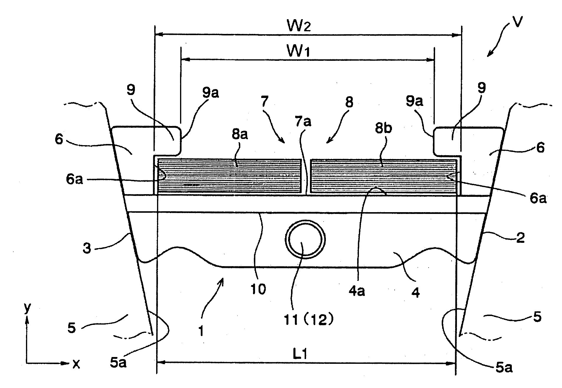
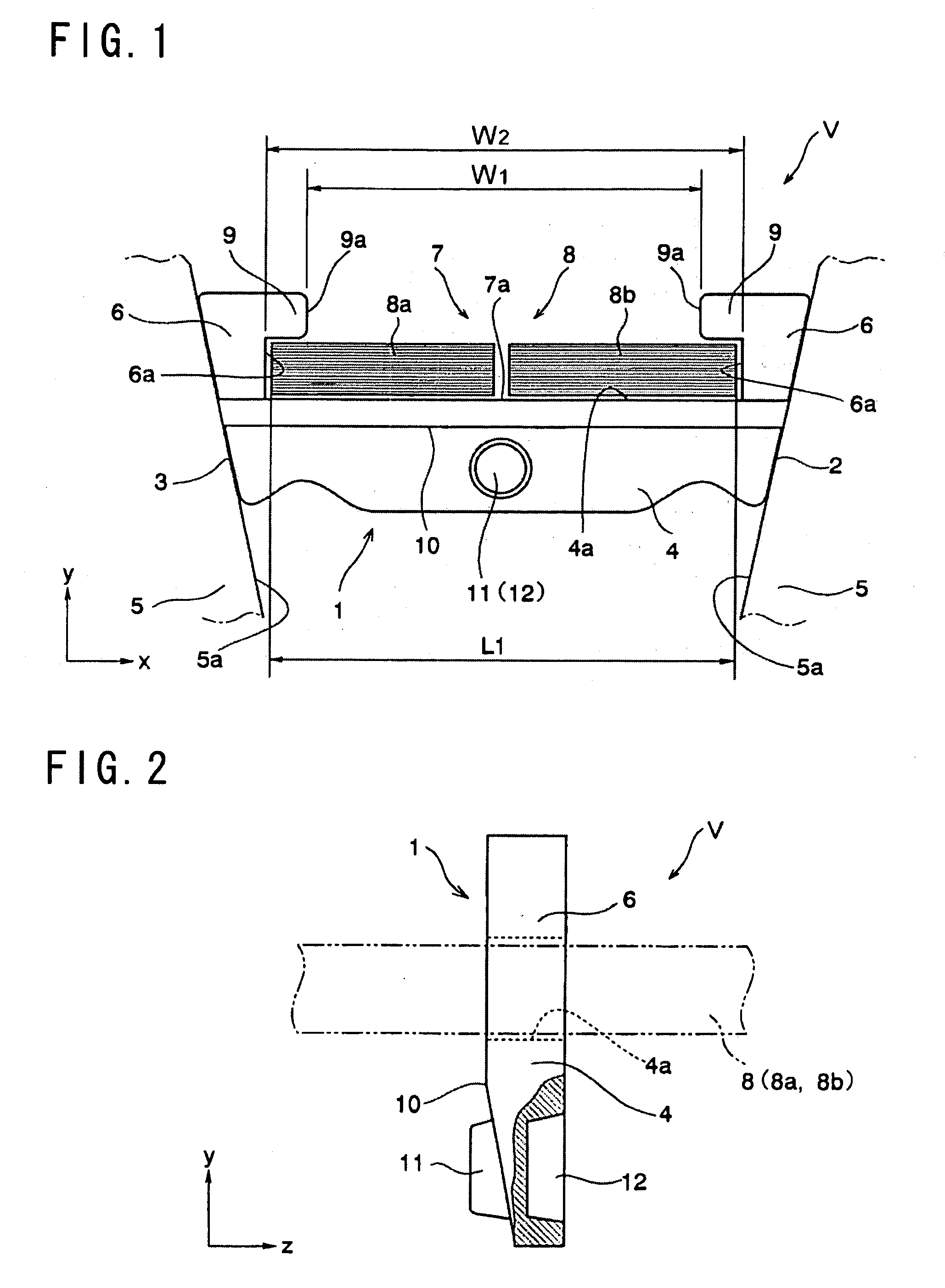
[0042]Here will be explained configurations of an element and a ring constituting a driving belt of the first example with reference to FIGS. 1 and 2. FIG. 1 shows an example of a driving belt V to be applied to a drive pulley (i.e., an input shaft side pulley) and a driven pulley (i.e., an output shaft side pulley) of a belt type continuously variable transmission so as to transmit a power between those pulleys. An element 1 is a metal plate member comprising a base portion (or main body) 4. Both lateral faces 2 and 3 of the base portion 4, that is, both lateral ends (in the direction of x-axis in FIG. 1) of the base portion 4 are inclined. The inclined lateral faces 2 and 3 are frictionally contacted with a V-shaped groove of a drive or driven pulley 5 of the belt type continuously variable transmission to transmit a torque.

[0043]The base portion 4 comprises columns 6 erected vertically (in the direction of y-axis in FIGS. 1 and 2) at both lateral ends (in the direction of x-axis ...

second example

[0058]Here will be explained the second example of the element and the ring of the driving belt with reference to FIGS. 5 and 6. According to the above-explained first example, the male and female connections 11 and 12 are formed respectively on the center of width of the base portion 4. On the other hand, according to the second example to be described, the male and female connections are formed on a portion other than the center of width of the base portion 4 of the element 1. The remaining elements of the second example are identical to those of the first example shown in FIGS. 1 and 2, so further explanation of the elements in common with the first example will be omitted by allotting common reference numerals.

[0059]In the example shown in FIGS. 5 and 6, one male connection and one female connection which are structurally identical to those of the first example are individually formed on each flat face of one of the column 6 (i.e., on the right column in FIG. 5) being opposed to...

third example

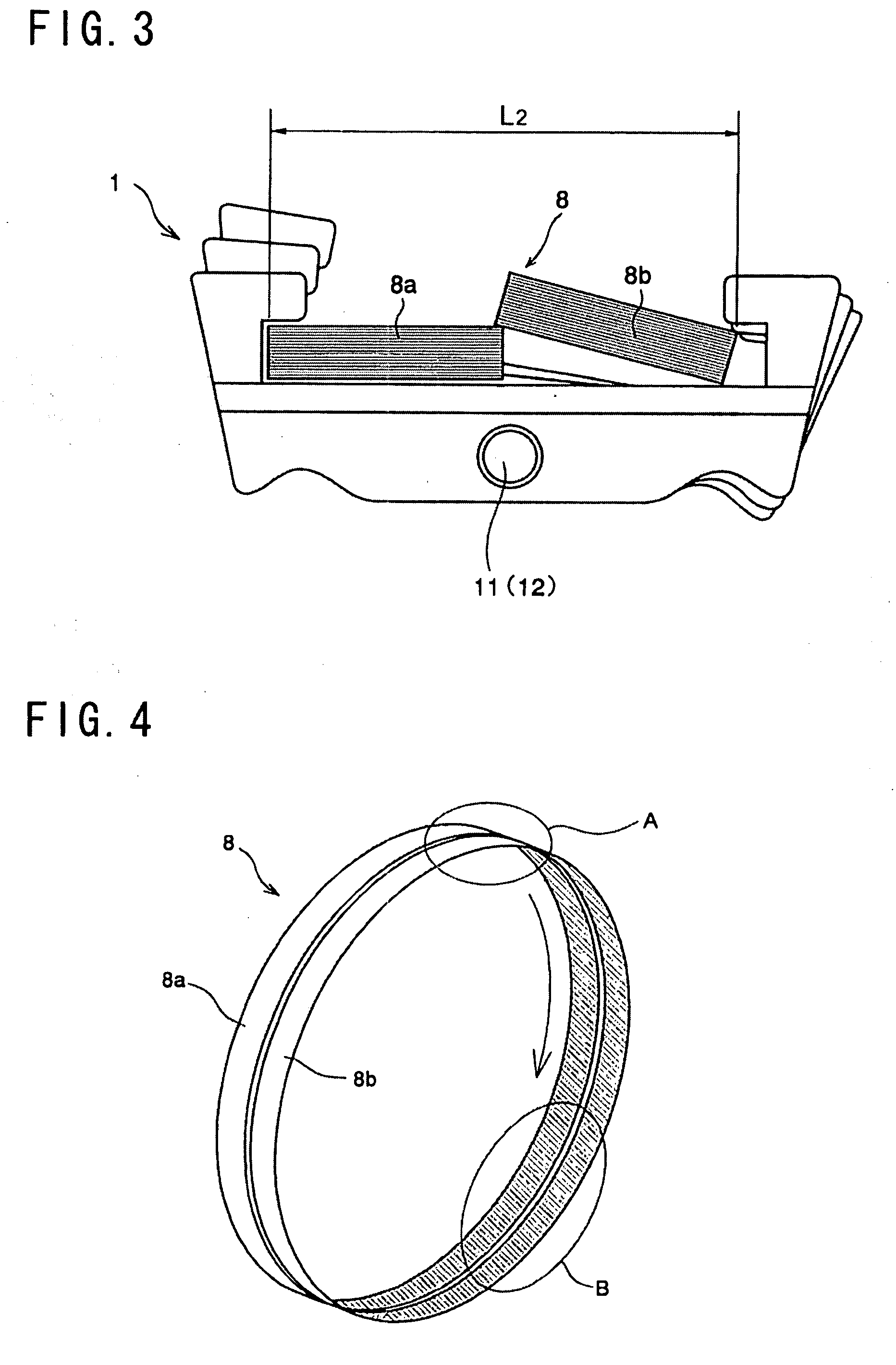
[0062]Here will be explained a third example of the element and the ring of the driving belt with reference to FIGS. 7 and 8. According to the previously described first example, the width of both rings 8a and 8b constituting the ring 8 is entirely constant. On the other hand, according to the third example, the ring also comprises two rings but each ring comprises two layers of different widths. Specifically, the width of both inner rings is constant entirely, and a width of each outer ring is also constant entirely but narrower than that of the inner ring. The remaining elements of the third example are identical to those of the first example shown in FIGS. 1 and 2, so further explanation of the elements in common with those in the first example will be omitted by allotting common reference numerals.

[0063]In the example shown in FIG. 7, two lines of rings 31a and 31b are used to constitute a ring 31 instead of the rings 8a and 8b of the first example. As shown in FIG. 7, outer rin...


PUM

PropertyMeasurementUnit
widthaaaaaaaaaa
speedaaaaaaaaaa
transmissionaaaaaaaaaa

Abstract

A driving belt and method of assembling the same, which can fit a ring with elements easily, and which can prevent detachment of the ring from the elements. In a driving belt, an endless ring is accommodated in a recess of elements arranged annularly in a manner to situate the recess to open to an outer circumferential side, and the elements are interlinked pivotally with respect to an opposed face of an adjoining element.

Description

TECHNICAL FIELD[0001]This invention relates to a driving belt, in which a plurality of plate elements interlinked with one another in a circular manner is fastened by an endless annular ring, and to an assembling method thereof.BACKGROUND ART[0002]In the prior art, a geared transmission capable of changing a gear stage thereof stepwise, and a continuously variable transmission capable of varying a speed change ratio steplessly are available as a transmission mechanism for transmitting power between rotary members. For example, a belt-type continuously variable transmission and a toroidal-type continuously variable transmission are known as the continuously variable transmission. Specifically, the belt-type continuously variable transmission is a transmission varying a speed change ratio continuously using a pair of drive pulleys and a pair of driven pulleys, and a driving belt applied to those pulleys. The known endless driving belt used in such belt-type continuously variable trans...

Claims


Application Information

Patent Timeline
Patent Type & Authority Applications(United States)
IPC IPC(8): F16G5/18B23P11/00
CPCY10T29/49826F16G5/16F16G5/00
Inventor KOBAYASHI, DAISUKE
Owner TOYOTA JIDOSHA KK
Why Eureka
Try Eureka