Plant cultivating unit and plant cultivating container

a technology for cultivating containers and plants, applied in the field of plant cultivating units, can solve problems such as urban residents' lives and considerable problems, and achieve the effects of preventing irregular water supply between plant cultivating units, promoting greening, and ensuring the safety of residents

Inactive Publication Date: 2009-10-22
SUNTORY HLDG LTD
View PDF11 Cites 44 Cited by
  • Summary
  • Abstract
  • Description
  • Claims
  • Application Information

AI Technical Summary

Benefits of technology

This patented technology allows multiple plant growing devices to be installed together without requiring external pipe lines. Each device contains its own water tank where water can flow freely from different sources depending upon factors like temperature and humidity levels during use. By allowing this fluid communication among them, any issues related to water supply may become apparent even after installation. Additionally, the system includes feature arrangements for easy accessibility within buildings' basement walls while also ensuring proper water supply based on environmental needs. Overall, this design improves efficiency and flexibility in managing indoor garden systems.

Problems solved by technology

Technological Problem addressed in this patented technical solution describes how air pollution caused by excessive temperatures can affect people living near populated locations or cause damage from rainwater runoff during times when there may be no use for public spaces nearby.

Method used


Image

  • Plant cultivating unit and plant cultivating container
  • Plant cultivating unit and plant cultivating container
  • Plant cultivating unit and plant cultivating container

Examples


first embodiment

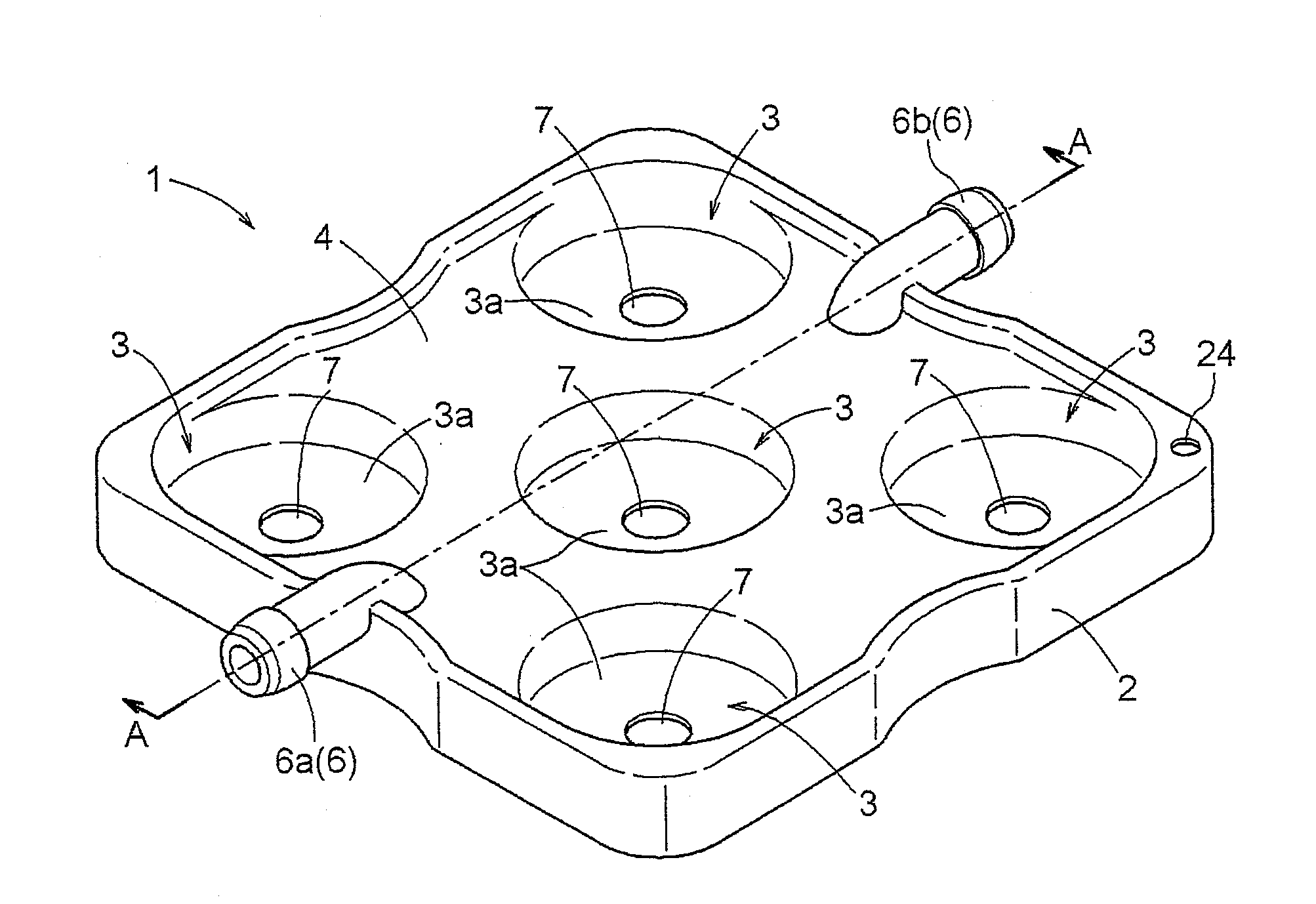
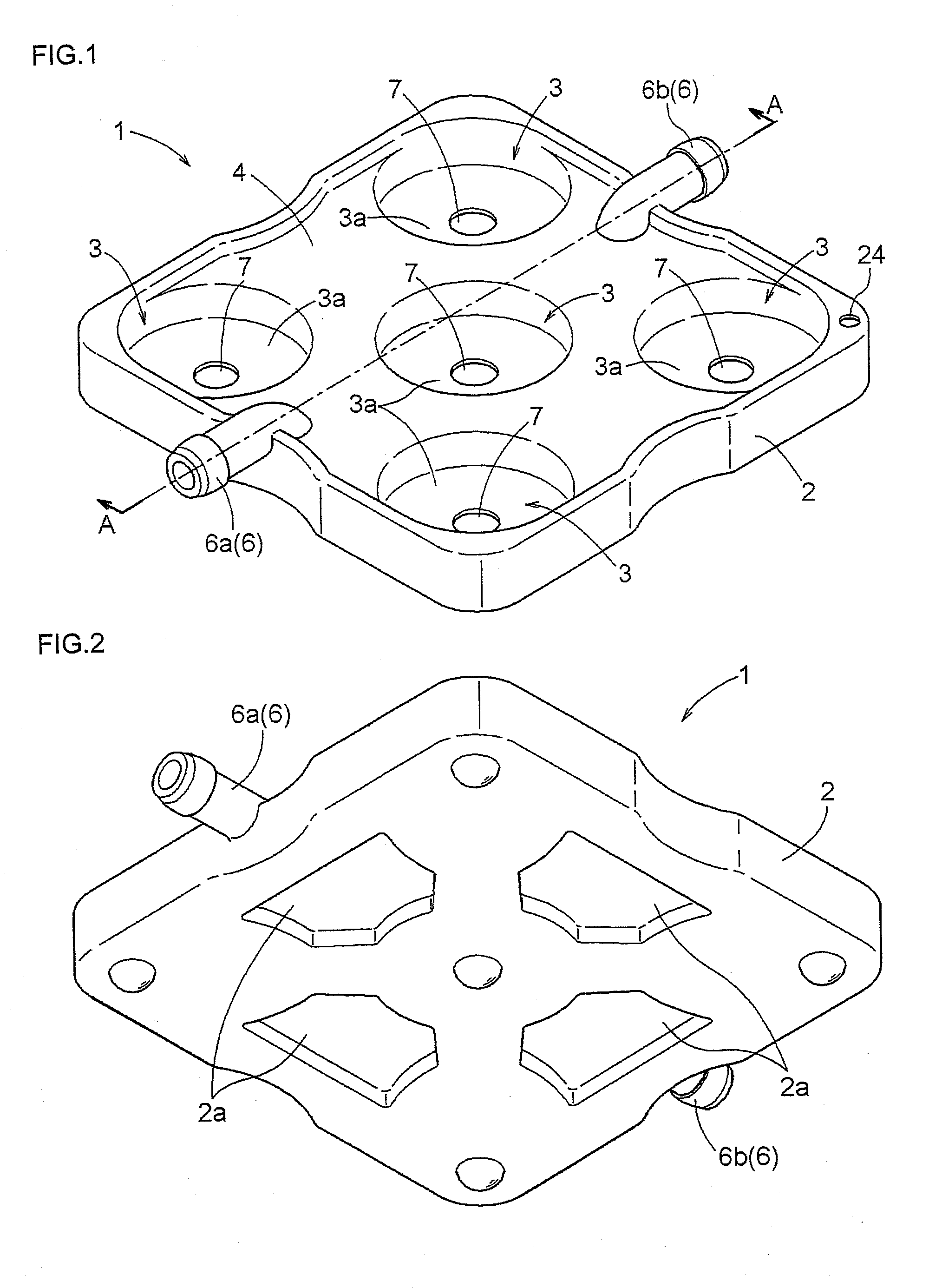
[0106]FIGS. 1 and 2 show a first embodiment of a plant cultivating unit 1 of the present invention (FIG. 1 shows the front side, and FIG. 2 shows the reverse side). The plant cultivating unit 1 is configured from a water storage tray 2 capable of storing water for watering plants P, a plurality of circular receivers 3 that can house a cultivating bottom layer 5 capable of sustaining the plants P, and a cover 4 that covers the top of the water storage tray 2. Raised-up bottom parts 2a are also formed between the receivers 3 in the water storage tray 2, as shown in FIG. 2.

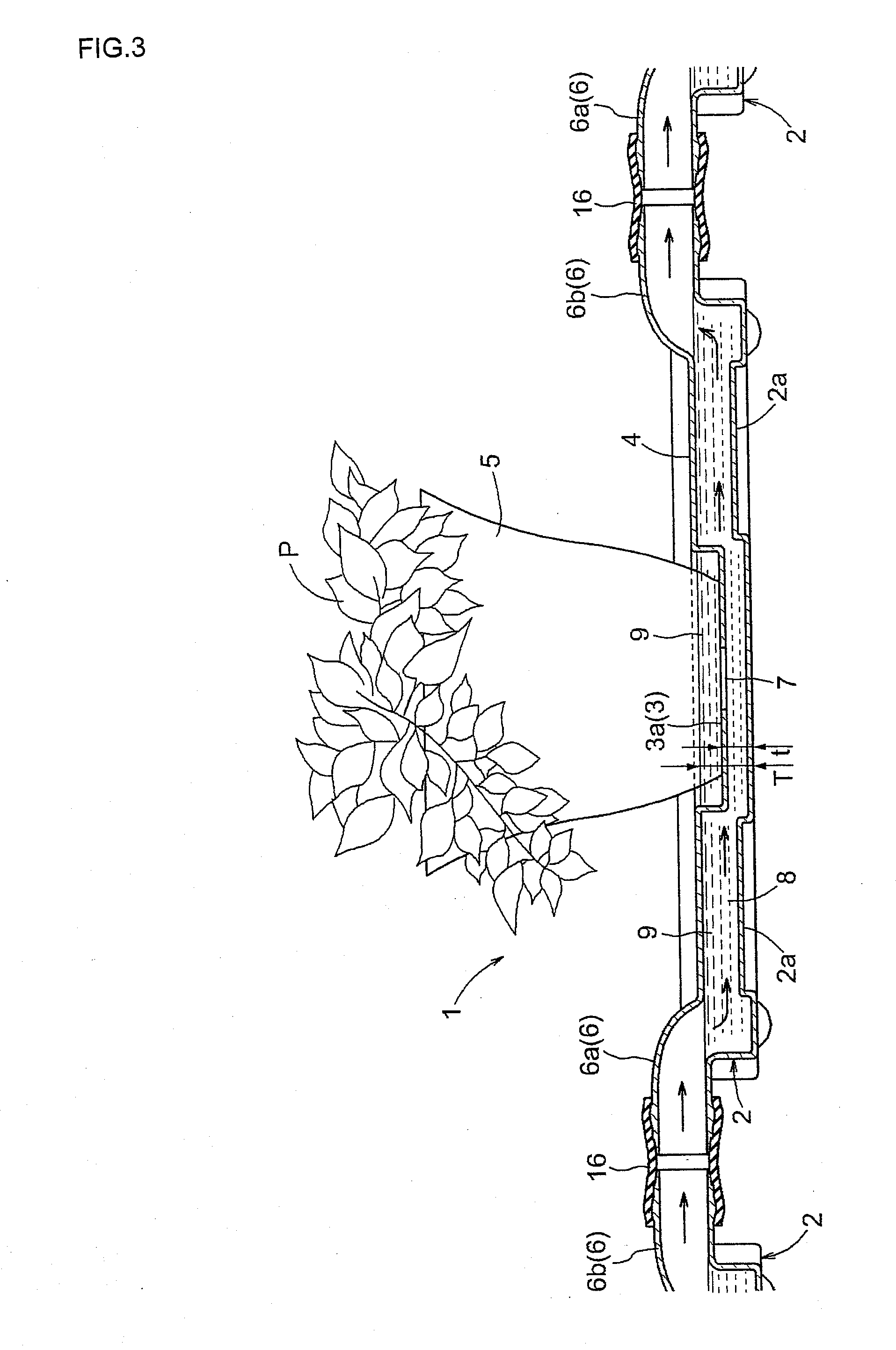
[0107]FIG. 3 is a schematic depiction of the cross section of the plant cultivating unit 1 indicated by arrow line A in FIG. 1 in a state in which the cultivating bottom layer 5 is housed in the receivers 3.

[0108]Possible examples of the cultivating bottom layer 5 include plant pots, planters, or the like that are filled with suitable planting soil and that have holes in the bottom, or planting soil that is used alon...

second embodiment

[0116]FIGS. 4 through 9 show the second embodiment of the plant cultivating unit 1 of the present invention.

[0117]As shown in FIG. 4, the plant cultivating unit 1 of the second embodiment is configured from a water storage tray 2 capable of storing water for watering plants, and an integrally molded plant cultivating container 14 (an integrally molded component in which a plurality of receivers 3 that can house a cultivating bottom layer 5 capable of sustaining plants P is molded integrally with a cover 4 for covering the top of the water storage tray 2). The water storage tray 2 and the plant cultivating container 14 can be detachably fitted together.

[0118]FIG. 5 is a schematic cross section of the plant cultivating unit 1 (in a state in which the water storage tray 2 and plant cultivating container 14 are fitted together) of the second embodiment indicated by the arrow line B in FIG. 4, in a state in which the cultivating bottom layer 5 is housed in the receivers 3.

[0119]As shown ...

third embodiment

[0140]FIGS. 11(A),(B), and 12 show the third embodiment of the plant cultivating unit 1 of the present invention. Similar to the embodiment described above, the plant cultivating unit 1 is configured from a water storage tray 2 capable of storing water for watering plants, a plurality of circular receivers 3 that can house a cultivating bottom layer capable of sustaining plants, and a cover 4 that covers the top of the water storage tray 2, as shown in FIG. 11(A).

[0141]The water storage tray 2 is provided with two connecting nozzles 6 (connectors) that can communicably connect adjacent water storage trays 2 to each other, and the connecting nozzles 6 are further distinguished into an inflow connecting nozzle 6a (inflow connector) and an outflow connecting nozzle 6b (outflow connector) according to the direction in which water flows.

[0142]Furthermore, the water storage tray 2 is provided with mounting parts 17 (mounting convexities 17a and mounting concavities 17b), and is configured...


PUM


Abstract

An object of the present invention is to provide a plant cultivating unit that can perform a watering operation in a simple manner and can supply water uniformly to plants in locations where a floor surface is sloped, such as the rooftop of a building, without requiring separate water supply piping work. A plant cultivating unit (1) comprises a water storage tray (2) in which water can be stored and in which receivers (3) for housing the roots of plants can be arranged in an interior thereof, a water storage space (8) in the water storage tray (2) and the receivers (3) being communicated via water feeders (7), and the water stored in the water storage space (8) being able to be supplied to the plants via the water feeders (7). The water storage tray (2) is provided with connectors (6) capable of communicably connecting adjacent water storage trays (2) to each other, the connectors (6) being configured from an inflow connector (6a) and an outflow connector (6b), the water flowing in through the inflow connector (6a) to the water storage space (8), and the water being able to flow out through the outflow connector (6b) by an overflow when a specific amount of water is stored in the water storage space (8).

Description


Claims


Application Information

Patent Timeline
Owner SUNTORY HLDG LTD
Why Eureka
Try Eureka