Road Bicycle Handlebar

Inactive Publication Date: 2009-10-22
TIEN HSIN INDS
View PDF7 Cites 0 Cited by
  • Summary
  • Abstract
  • Description
  • Claims
  • Application Information

AI Technical Summary

Benefits of technology

[0009]The primary objective of the present invention is to provide a road bicycle handlebar covered with a cushion to make the holding more comfortable.
[0010]The second objective of the present invention is to provide a road bicycle handlebar utilizing two spherical cushions respectively mounted on a brake control handle and a gear shift handle to make the riding more comfortable.
[0011]The third objective of the present invention is to provide a road bicycle handlebar defined with a groove for placement of fingers of the hand to allow the hand of the rider to be always maintained in a ready-to-press-the-brake-control-handle state to improve the riding safety.

Problems solved by technology

So if the handle cannot effectively reduce the pressure from the rider's weight and absorb the shake caused during the riding process, the rider must feel uncomfortable.
In addition, during the riding process, since the brake control handle 12 is not defined with a concave structure for placement of fingers of the hand 20, the rider must grip the base 10 with the thumb (not shown) and other fingers of the hand 20 and is unable to keep his / her fingers always in a ready-to-press-the-brake-control-handle state, as a result, in case of crisis, the rider probably cannot press the brake control handle 12 to produce an emergency braking as quick as needed, thus increasing the riding danger.

Method used


Image

  • Road Bicycle Handlebar
  • Road Bicycle Handlebar
  • Road Bicycle Handlebar

Examples


Embodiment Construction

[0017]The present invention will be clearer from the following description when viewed together with the accompanying drawings, which show, for purpose of illustrations only, the preferred embodiment in accordance with the present invention.

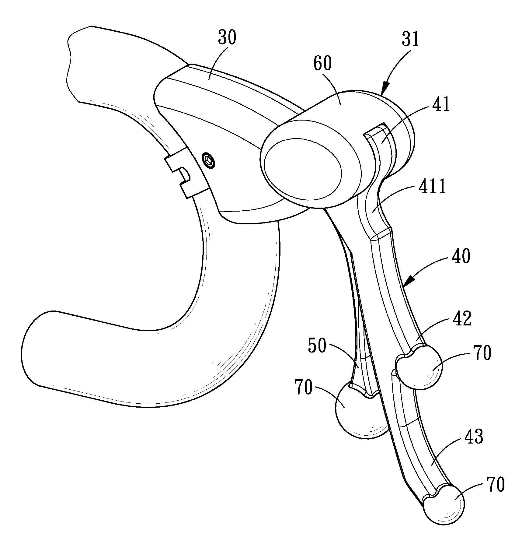
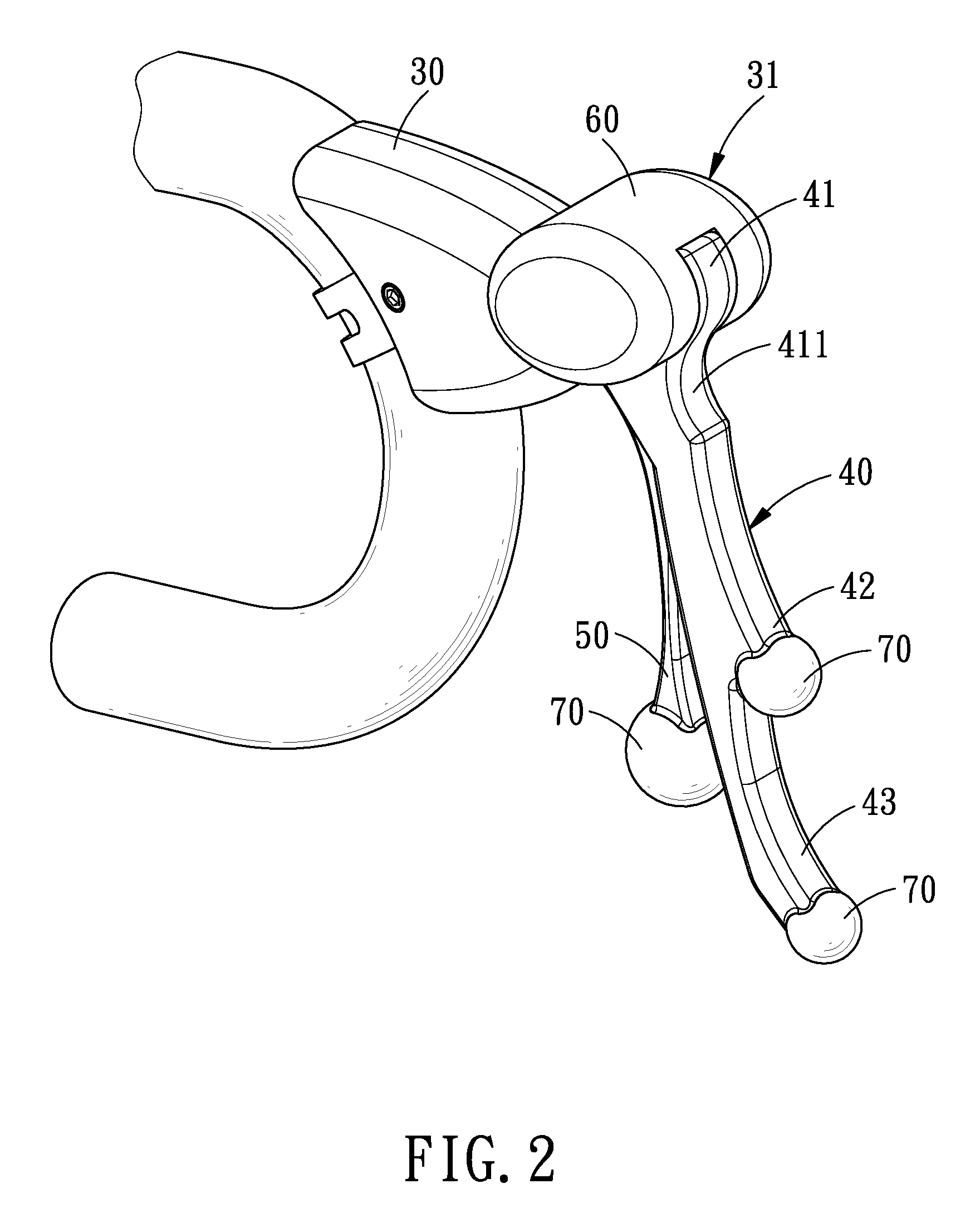
[0018]Referring to FIGS. 2-4, a road bicycle handle in accordance with a preferred embodiment of the present invention is shown and comprises a base 30, a brake control handle 40, a gear shift handle 50, a cushion 60 and three spherical cushions 70.

[0019]The base 30 has a holding portion 31.

[0020]The brake control handle 40 includes an upper end 41, a middle portion 42 and a lower end 43. The upper end 41 is pivotally coupled to the holding portion 31 of the base 30 and defined in an outer edge thereof with a groove 411 for placement of a forefinger 81 of a hand 80. The groove 411 is open toward a running direction of the road bicycle.

[0021]The gear shift handle 50 is pivotally coupled to the holding portion 31 of the base 30 and is located adjac...


PUM


Abstract

A road bicycle handlebar comprises a base, a brake control handle, a gear shift handle, a cushion and three spherical cushions. The cushion covers a holding portion of the base for making the holding more comfortable. The three spherical cushions are respectively assembled on the brake control handle and the gear shift handle to make the riding more comfortable. The brake control handle is defined with a groove for placement of fingers of the hand to allow the hand of the rider to be always maintained in a ready-to-press-the-brake-control-handle state, thus improving the riding safety.

Description

[0001]This application is a continuation of part of U.S. patent application Ser. No. 11 / 620,611, which claims the benefit of the earlier filing date of Jan. 05, 2007. Claim 1 of this application is revised from claim 1 of the U.S. patent application Ser. No. 11 / 620,611, claim 2 of this application is new, and claim 3 of this application corresponds to claim 2 of the U.S. patent application Ser. No. 11 / 620,611.BACKGROUND OF THE INVENTION[0002]1. Field of the Invention[0003]The present invention relates to a handlebar, and more particularly to a road bicycle handlebar.[0004]2. Description of the Prior Art[0005]Bicycles are generally divided into mountain bicycle (also called cross-country bicycle) and road bicycle (also called roadster or racing bicycle) according to function. Here we are going to discuss about the road bicycle only.[0006]Referring to FIG. 1, a conventional handlebar comprises a brake control handle 12 and a gear shift handle 13 which are pivotally connected to a hold...

Claims


Application Information

Patent Timeline
IPC IPC(8): B62K21/26B62K21/12
CPCB62K21/125Y10T74/20822B62M25/04B62K23/06B62L3/02
Inventor CHIANG, CHENG-HSUN
Owner TIEN HSIN INDS
Why Eureka
Try Eureka