Ski lift having an auxiliary conveyor floor

a conveyor floor and lift technology, applied in the direction of conveyors, conveyor parts, rope railways, etc., can solve the problems of not always being able to guide a sufficiently long conveyor floor from behind, not always being able to provide space,

Inactive Publication Date: 2009-10-22
CHAIRKID FORDERTECHN
View PDF15 Cites 6 Cited by
  • Summary
  • Abstract
  • Description
  • Claims
  • Application Information

AI Technical Summary

Benefits of technology

[0005]Starting from this, it is the underlying object of the present invention to provide an improved passenger conveying system, in particular a ski lift system, of the initially named type which avoids disadvantages of the prior art and further develops the latter in an advantageous manner. A simple and safe boarding should also in particular be achieved under tight space relationships in the region of the boarding platform of the chair lift or of the circulating gondola lift.

Problems solved by technology

A problem to be solved here, however, is the boarding of the circulating conveyor or the disembarking therefrom since as a rule high circulation speeds have to be operated to achieve the high conveying rates.
Particularly with older chair lift systems, but also with circulating gondola lifts, this space is, however, not always present.
In particular when the cable is caught or attached directly behind the reversing wheel of the circulating conveyor by means of tensioning weights positioned there, it is not possible to guide a sufficiently long conveyor floor from behind in the conveying direction into the boarding zone or, with crossways boarders, transversely to the conveying direction of the main conveyor below its reversing wheel.

Method used


Image

  • Ski lift having an auxiliary conveyor floor
  • Ski lift having an auxiliary conveyor floor
  • Ski lift having an auxiliary conveyor floor

Examples


Embodiment Construction

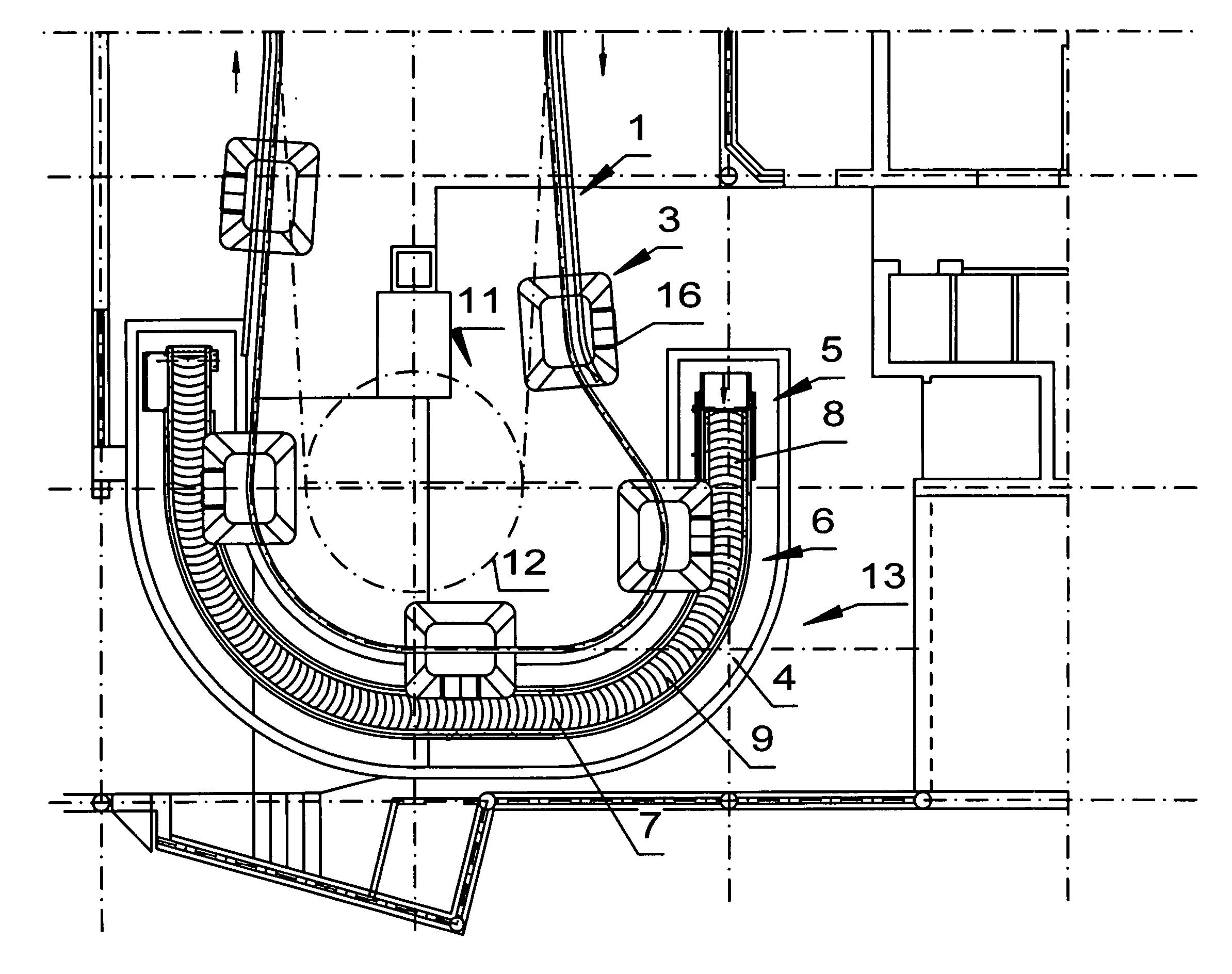
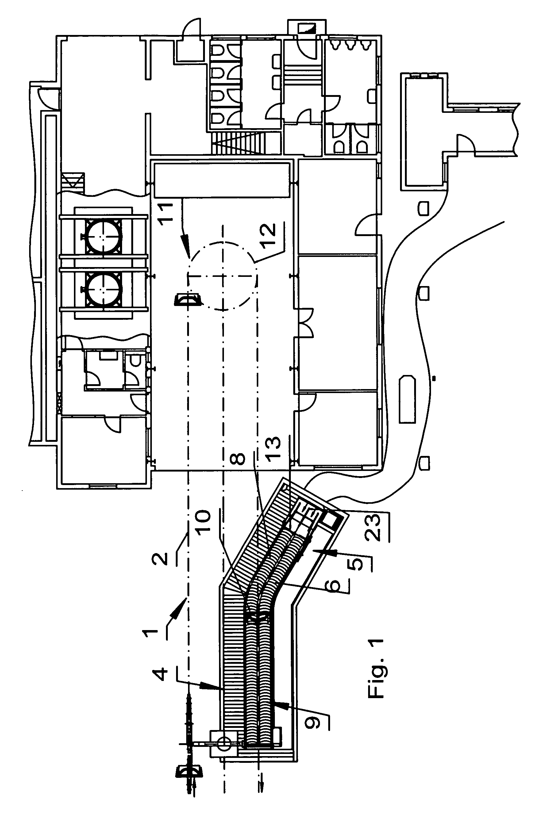
[0035]FIG. 1 shows the lower terminal of a chair lift system. The chair lift 2 forming the main conveyor 1 comprises a circulating carrier cable or conveyor cable which is deflected in the terminal building 2 by means of a reversal device 11, more precisely by means of a reversing carousel 12.

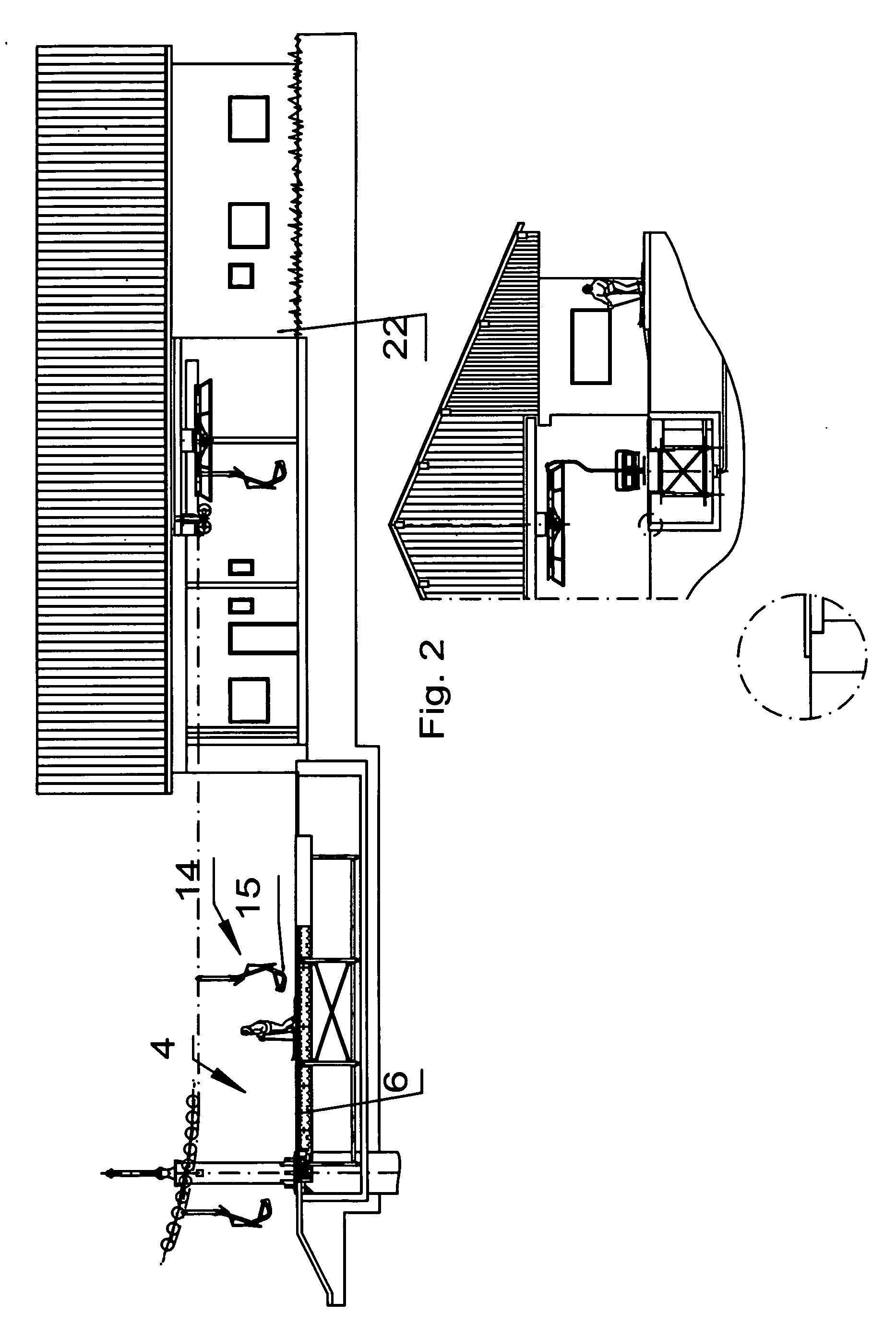
[0036]In the embodiment shown, the boarding zone for the boarding of the chair lift 2 is arranged outside the named terminal building 22. A boarding / disembarking platform 4 is arranged beneath the run of the carrier cable running downhill and is matched vertically to the chair lift 2 such that its passenger carrier means 14 run in the form of the chair 15 at a suitable level over the boarding platform 4, cf. FIG. 2.

[0037]In this respect a conveyor floor 6, which describes a curved conveyor path 7, as FIG. 1 shows, is associated with the named boarding / disembarking platform 4 as an auxiliary conveyor 5 for the transport of the passengers. The access region of the conveyor floor 6 is disposed lat...


PUM


Abstract

The present invention relates to a passenger transportation system, in particular a ski lift system in the form of a chair lift system or a circulating gondola lift system, having a main conveyor, in particular a chair lift or a circulating gondola lift, having a boarding/disembarking platform to board and/or alight from the main conveyor moving past the boarding/disembarking platform as well as having an auxiliary conveyor in the form of a conveyor floor for the conveying of persons to and/or from the boarding/disembarking platform. It is proposed in accordance with the invention that the conveyor floor describes a curved conveyor path which includes a first conveyor path section which feeds to the boarding platform or feeds away from the disembarking platform at an acute angle inclined to the conveying direction of the main conveyor and a second conveyor path section which extends substantially parallel to the conveying direction of the main conveyor at the boarding platform.

Description

BACKGROUND OF THE INVENTION[0001]The present invention relates to a passenger transportation system, in particular a ski lift system in the form of a chair lift or circulating gondola lift system, having a main conveyor, in particular a chair lift or a circulating gondola lift, having a boarding / disembarking platform to board and / or alight from the main conveyor moving past the boarding / disembarking platform as well as having an auxiliary conveyor in the form of a conveyor floor for the conveying of persons to and / or from the boarding / disembarking platform.[0002]In ski lift systems of the named type, as a rule circulating conveyors, for example in the form of a chair lift or of a circulating gondola lift, are used to achieve high passenger conveying rates. A problem to be solved here, however, is the boarding of the circulating conveyor or the disembarking therefrom since as a rule high circulation speeds have to be operated to achieve the high conveying rates. To combat this proble...

Claims


Application Information

Patent Timeline
Patent Type & Authority Applications(United States)
IPC IPC(8): B66B29/08
CPCB61B12/022B66B23/10B66B21/10B65G17/086
Inventor HUBER, MANFRED
Owner CHAIRKID FORDERTECHN
Why Eureka
Try Eureka