Light source driving device

a driving device and light source technology, applied in the direction of light sources, lighting apparatus, instruments, etc., can solve the problems of increasing cost and unit size, increasing aging, shortening the life of components,

Inactive Publication Date: 2009-10-22
AMPOWER TECH CO LTD
View PDF4 Cites 43 Cited by
  • Summary
  • Abstract
  • Description
  • Claims
  • Application Information

AI Technical Summary

Benefits of technology

[0019]The transformer circuit 406 is connected to the DC / AC convert circuit 405 to isolate the AC signal output from the DC / AC convert circuit 405. Transformer circuit 406 comprises an isolated transformer T1 having a primary winding and a secondary winding. The primary winding of the isolated transformer T1 is connected the DC / AC converting circuit 405, and the secondary winding thereof is connected to the resonance balancing circuit 407. Alternatively, the isolated transformer T1 can have a plurality of secondary windings. According to safety rules, the isolated transformer T1 isolates the AC power source 400 from the light source module 414 and the resonance balancing circuit 407, in order to protect the light source module 414 and the resonance balancing circuit 407.

Problems solved by technology

In this way, components of the DC / AC converting circuit 111 are switched frequently, which accelerates aging and shortens life of the components.
In addition, there is need for a current feedback circuit in the light source driving device, which increases cost and unit size.

Method used


Image

  • Light source driving device
  • Light source driving device
  • Light source driving device

Examples


first embodiment

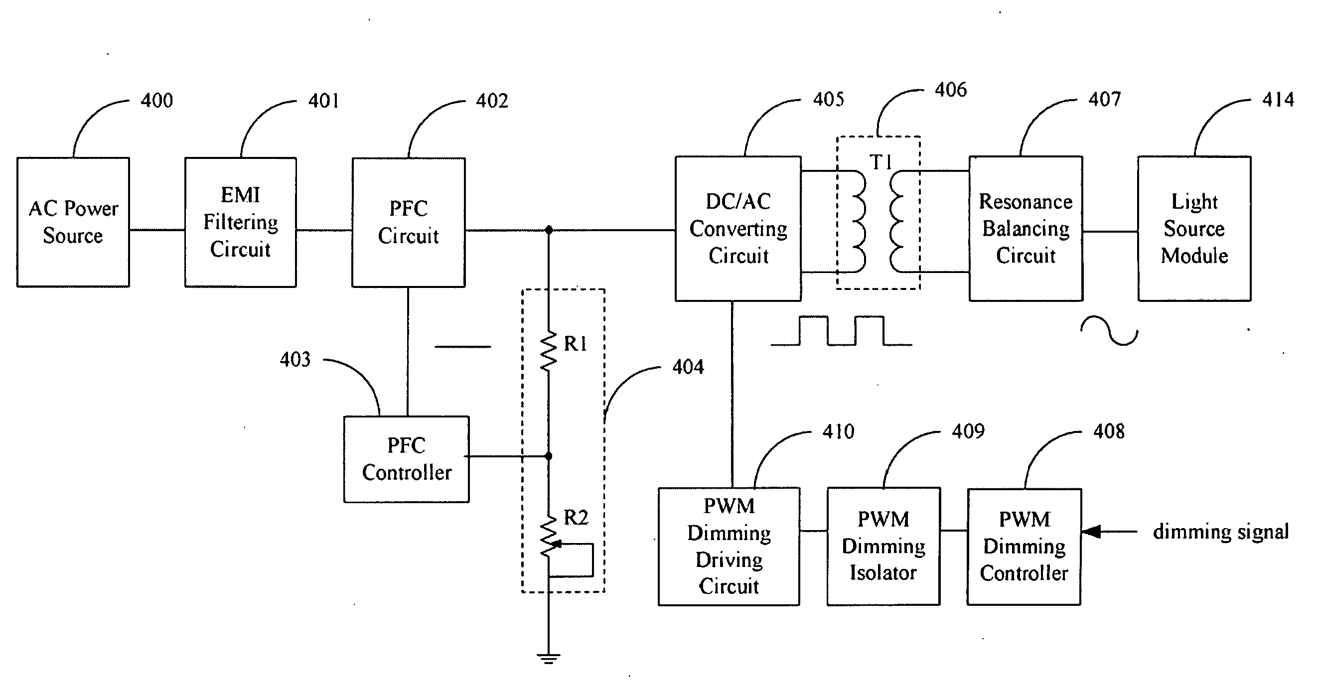
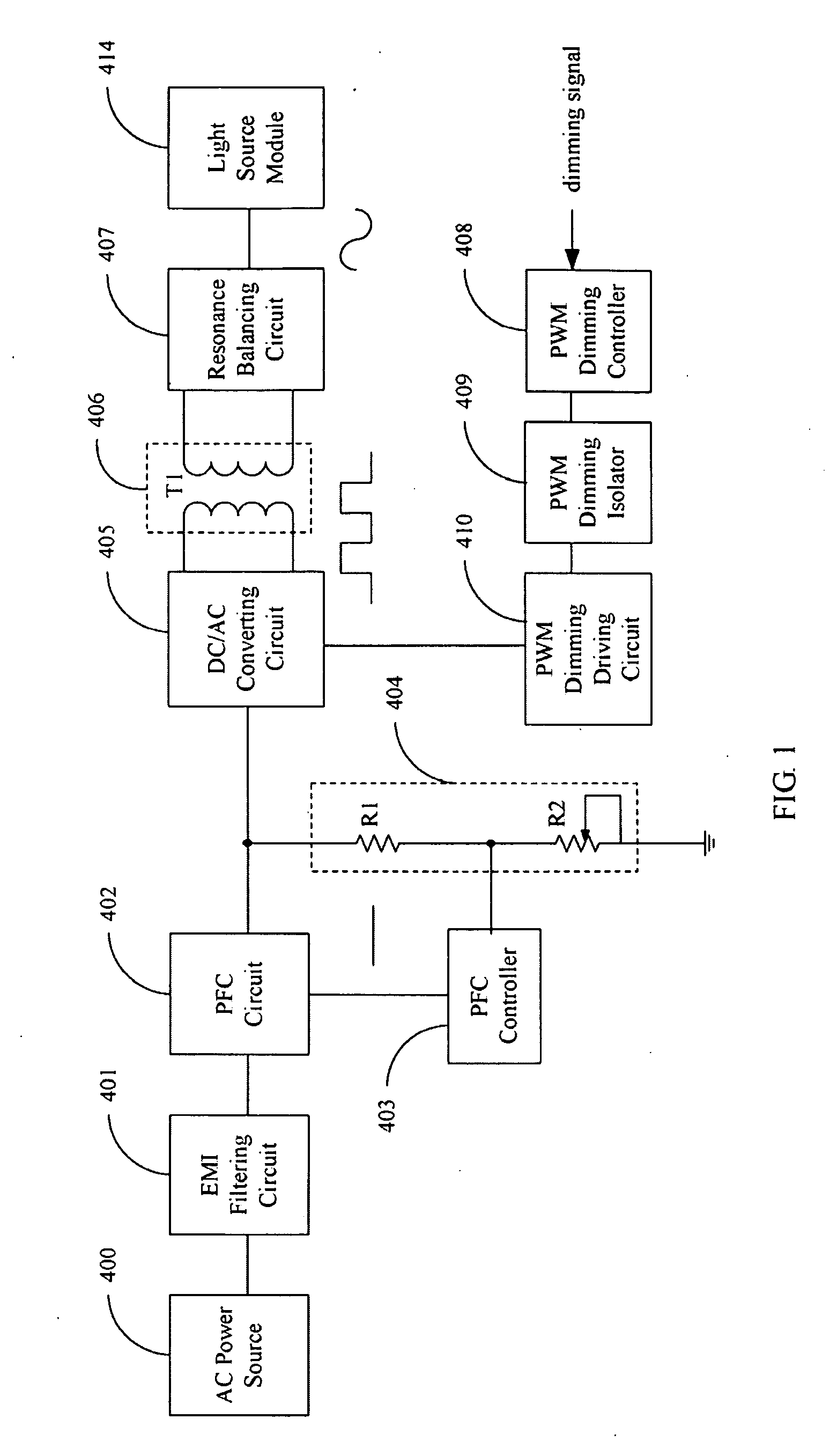
[0014]FIG. 1 is a block diagram of a light source driving device to drive a light source module 414 in accordance with the present disclosure. The light source driving device comprises an alternating current (AC) power source 400, an electromagnetic interference (EMI) filtering circuit 401, a power factor correction (PFC) circuit 402, a PFC controller 403, a voltage dividing circuit 404, a DC / AC converting circuit 405, a transformer circuit 406, a resonance balancing circuit 407, a PWM dimming controller 408, a PWM dimming isolator 408 and a PWM dimming driving circuit 410. The light source module 414 comprises a plurality of light sources, such as discharge lamps.

[0015]The AC power source 400 provides an electrical signal. The electrical signal is filtered via the EMI filtering circuit 401 and output to the PFC circuit 402. The EMI filtering circuit 401 is connected between the AC power source 400 and the PFC circuit 402 to filter EMI in the electrical signal. PFC circuit 402 is a ...

second embodiment

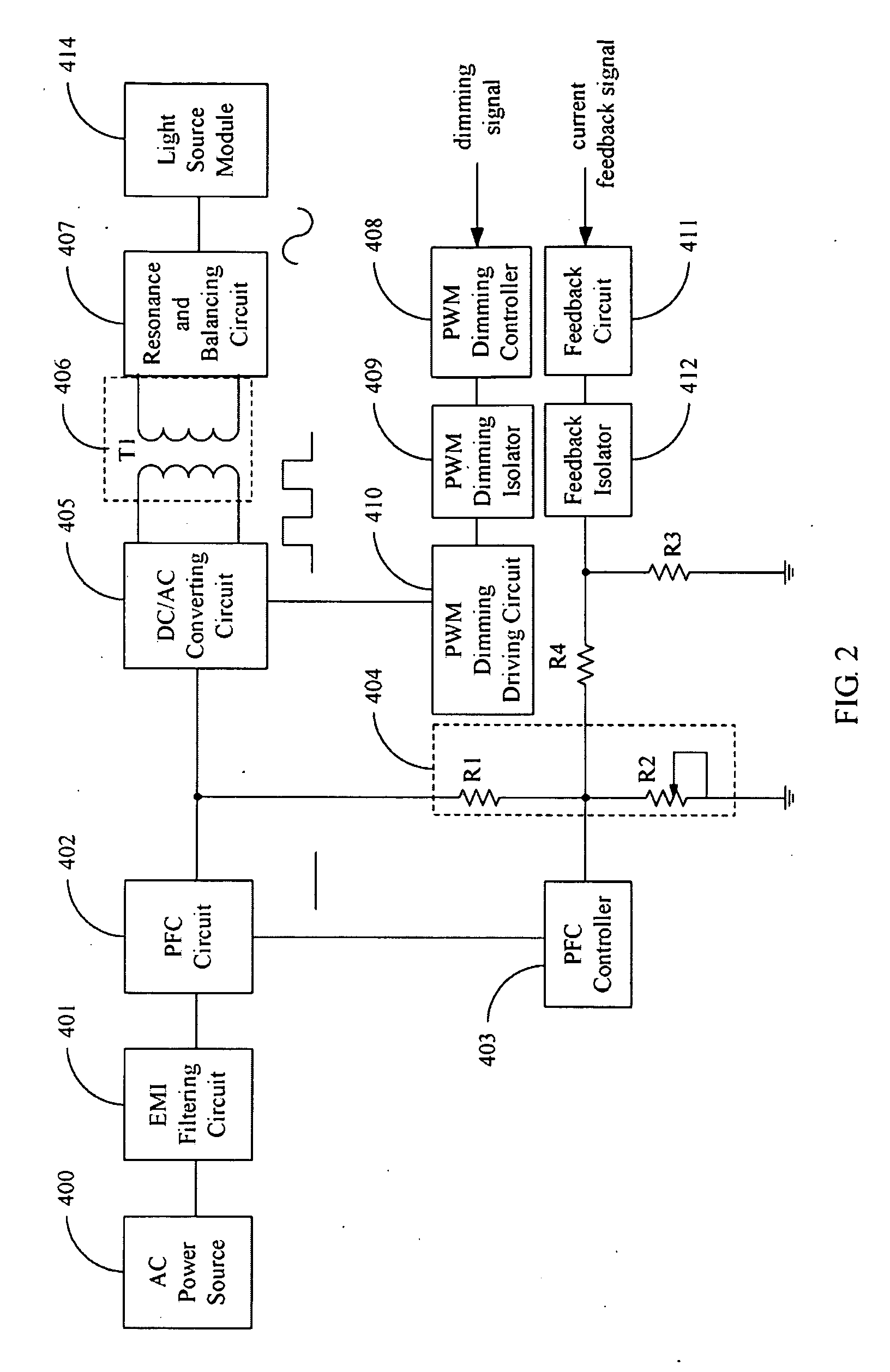
[0023]FIG. 2 is a block diagram of a light source driving device in accordance with the present disclosure, differing only from that of FIG. 1 in the inclusion of a feedback circuit 411, a feedback isolator 412, a third resistor R3 and a fourth resistor R4.

[0024]The feedback circuit 411 is connected to the voltage dividing circuit 404 via the feedback isolator 412 and the fourth resistor R4. The feedback circuit 411 receives a current feedback signal and provides it to the PFC controller 403. Here, the current feedback signal is detected by external equipment before use. The voltage dividing ratio of the voltage dividing circuit 404 is adjusted by the current feedback signal, with voltage of the divided signal input to the PFC controller 403 adjusted accordingly. Thus, the output of the PFC circuit 402 can be adjusted.

[0025]Here, the feedback isolator 412 isolates the feedback circuit 411 from the AC power source 400. The feedback isolator 412 can be an isolating transformer or a ph...

third embodiment

[0027]FIG. 3 is a block diagram of a light source driving device in accordance with the present disclosure, differing from that of FIG. 1 only in the inclusion of a detection circuit 413, an amplifier A1, and a fifth resistor R5.

[0028]The detection circuit 413 is connected to the DC / AC converting circuit 405 to detect current through the DC / AC converting circuit 405 and convert the detected current signal to a voltage signal. The amplifier A1 has an input and an output. The input of the amplifier A1 is connected to the detection circuit 413, and the output thereof is connected to one end of the fifth resistor R5 to amplify the voltage signal output from the detection circuit 413. The other end of the fifth resistor R5 is connected to a common junction of the PFC controller 403 and the first resistor R1 to adjust the amplified voltage signal. In other words, the fifth resistor R5 is connected between the output of the detection circuit 413 and the PFC controller 403 to adjust the amp...


PUM


Abstract

A light source driving device drives a plurality of light sources. A Power Factor Circuit (PFC) circuit converts a received electrical signal to a DC signal and output to a DC / AC converting circuit. The DC / AC converting circuit converts the DC signal to another AC signal, which is isolated by the transformer circuit. A resonance balancing circuit converts the AC signal output from the transformer circuit to another AC signal to drive the light source module. A PWM dimming controller outputs a control signal to control output of the DC / AC converting circuit according to a received dimming signal, wherein duty cycle of the control signal is fixed. A voltage dividing circuit adjustably divides voltage of the DC signal output from the PFC circuit. A PFC controller feeds the divided signal back to the PFC circuit to control the DC signal output from the PFC circuit.

Description

BACKGROUND[0001]1. Field of the Invention[0002]Embodiments of the present disclosure relate to light source driving devices, and particularly to a light source driving device integrated with an alternating current (AC) / direct current (DC) converter.[0003]2. Description of Related Art[0004]Conventionally, discharge lamps, such as Cold Cathode Fluorescent Lamps (CCFLs) and External Electrode Fluorescent Lamps (EEFLs) have been used as light sources for liquid crystal displays (LCDs). In LCD modules, current through the lamps is controlled by adjustment of a duty cycle of Pulse-Width Modulator (PWM) controller.[0005]FIG. 6 shows one such light source driving device to drive a light source module 14. The light source driving device comprises an AC power source 10, an AC / DC converter 11, an inverter circuit 12, a PWM dimming controller 13, a PWM dimming isolator 131, and a PWM dimming driving circuit 132. The AC / DC converter 11 comprises a Power Factor Correction (PFC) circuit 110, a DC / ...

Claims


Application Information

Patent Timeline
Patent Type & Authority Applications(United States)
IPC IPC(8): H05B37/02
CPCH05B41/3927
Inventor GER, CHIH-CHAN
Owner AMPOWER TECH CO LTD
Why Eureka
Try Eureka