Transfer apparatus, method for preventing leakage current of the transfer apparatus, and image forming apparatus including the transfer apparatus

a technology of transfer apparatus and leakage current, which is applied in the direction of printing, other printing apparatus, etc., can solve the problems of reducing the quality of the image formed on the recording paper, the paper to be bent in a wrinkled state, and the recording paper to be lifted, so as to prevent the leakage current of the transfer apparatus and hinder the movement of the recording member

Inactive Publication Date: 2009-10-22
RICOH KK
View PDF3 Cites 8 Cited by
  • Summary
  • Abstract
  • Description
  • Claims
  • Application Information

AI Technical Summary

Benefits of technology

[0013]In view of the above-described problems, it is an object of at least one embodiment of the present invention to provide a transfer apparatus, a method for preventing a leakage current of the transfer apparatus, and an image forming apparatus including the transfer apparatus, by which recording papers wasted for absorbing condensation are drastically reduced, and a leakage current caused by condensation on the transfer belt is resolved without significantly increasing the manufacturing cost and power consumption.
[0015]According to another aspect of the present invention, a method for preventing a leakage current of a transfer apparatus is provided. The transfer apparatus includes an endless belt to transfer a recording member by attaching the recording member on a surface thereof by an electrostatic force; and a driving device to rotate the endless belt. The method includes the steps of holding the recording member by a holding device to hinder a movement of the recording member caused by a movement of the endless belt rotated by the driving device such that a part of the recording member contacts the surface of the endless belt; rotating the endless belt by the driving device so that the part of the recording member slides on the surface of the endless belt; and releasing the recording member to be transferred out of the endless belt.

Problems solved by technology

The fibers swollen by the ink causes the recording paper to be bent in a wrinkled state (the wrinkled state is referred to as “cockling”), and may cause the recording paper to be lifted.
When the recording paper is lifted, landing positions of the discharged ink droplets are displaced from the predetermined positions or the recording paper contacts a recording head, resulting in drastically decreasing the quality of an image formed on the recording paper.
However, these ways have disadvantages of leading to an increase in printing cost.
However, when an inkjet printer and the like sufficiently cooled over night in winter are exposed to warm air emitted from a heating appliance such as an air conditioner, a gas heater, and an oil heater in the morning, condensation may form on the surface of the transfer belt since the transfer belt at a low temperature is exposed to the warm and humid air.
The condensation on the surface of the transfer belt leads to a leakage current generated when a high voltage is applied to the transfer belt.
However, when an instruction to start printing is received and a high voltage power source board is turned on, a leakage current flows through the condensation on the surface of the transfer belt.
A leakage detecting circuit provided in the high voltage power source detects this abnormality and registers an error.
However, this method has defects in that manufacturing cost is increased so that inexpensive types of printers cannot easily employ this method, current is consumed when the power is off, and the condensation preventing heater does not work when the main power of the apparatus is off.
However, this method requires plural sheets of recording paper to absorb the condensation.
Therefore, in order to transfer the recording paper to contact the interval part of the transfer belt, the transfer belt has to rotate plural times. In this case, many sheets of recording paper are wasted and a longer time is required.

Method used


Image

  • Transfer apparatus, method for preventing leakage current of the transfer apparatus, and image forming apparatus including the transfer apparatus
  • Transfer apparatus, method for preventing leakage current of the transfer apparatus, and image forming apparatus including the transfer apparatus
  • Transfer apparatus, method for preventing leakage current of the transfer apparatus, and image forming apparatus including the transfer apparatus

Examples


Embodiment Construction

[0026]An embodiment of the present invention is described in detail below.

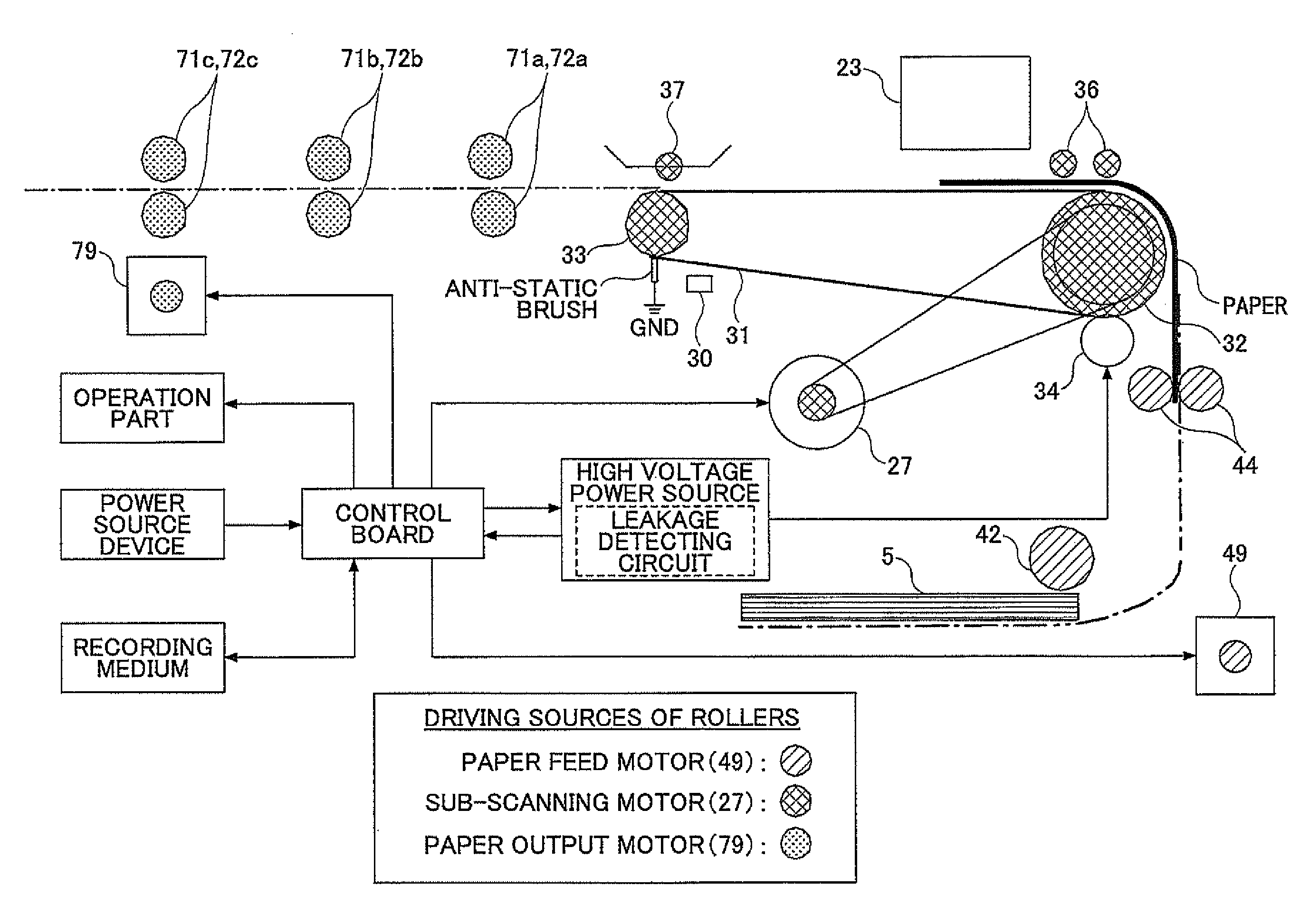
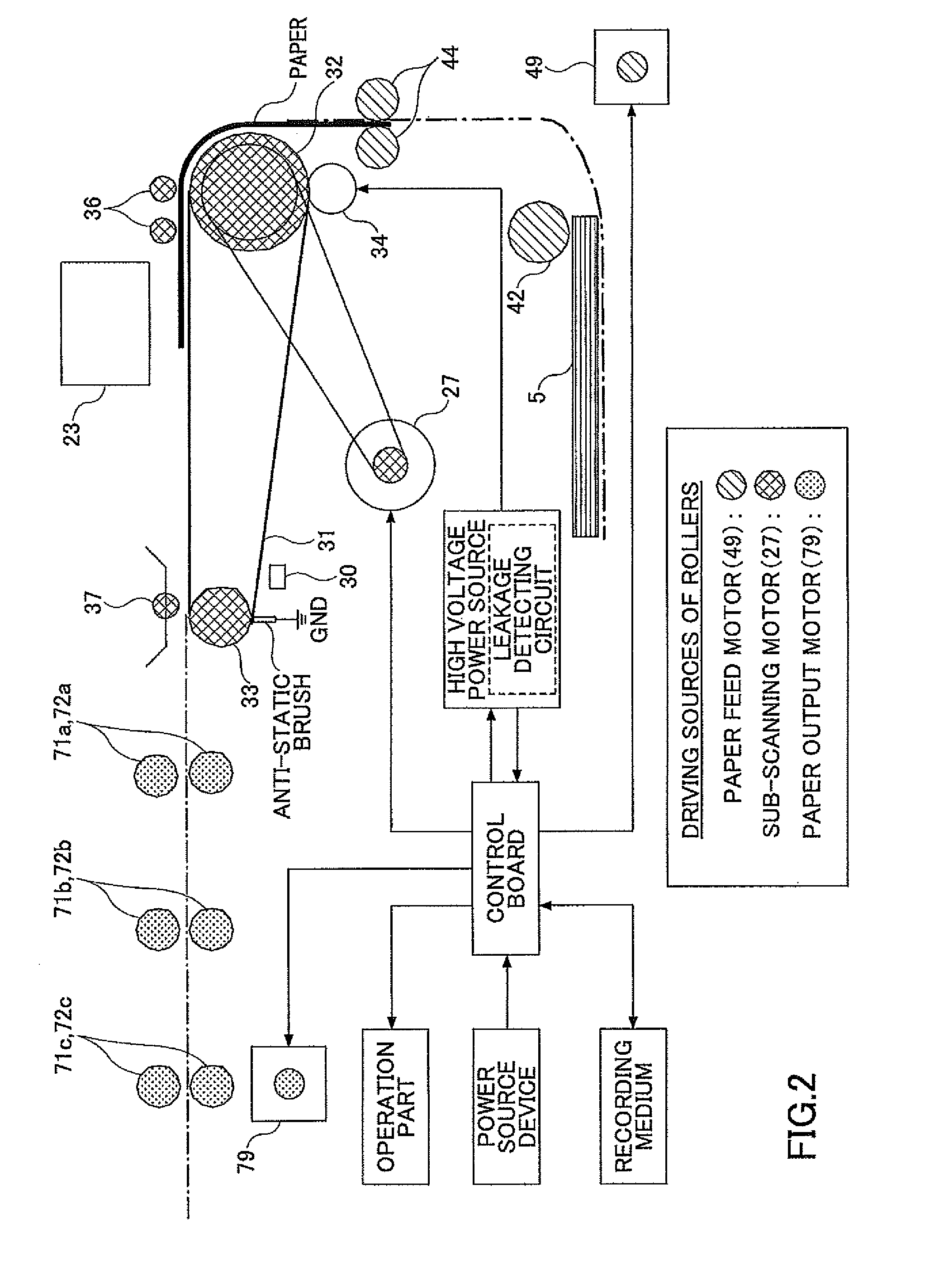
[0027]The present invention relates to a transfer apparatus used in an image forming apparatus and the like, to transfer a recording member and the like by attaching the recording member on an endless belt by applying a voltage onto a surface of the endless belt. A transfer apparatus of the embodiment of the present invention includes a driving device to stretch and rotate the endless belt; a power source to apply the voltage to the endless belt; a holding device to hold a moisture absorbing member at a predetermined position with a part or all of the moisture absorbing member contacting the surface of the endless belt; and a rotation amount measuring device to measure an amount of a rotation of the endless belt.

[0028]The endless belt is stretched by at least two rollers and the like. One of the two rollers, which serves as a driving roller, rotates the endless belt. Recording paper serving as the recording me...


PUM


Abstract

A disclosed transfer apparatus includes an endless belt to transfer a recording member by attaching the recording member on a surface thereof by an electrostatic force; a driving device to rotate the endless belt; and a holding device to temporarily hold the recording member to hinder a movement thereof caused by a movement of the endless belt rotated by the driving device so that a part of the recording member slides on the surface of the endless belt.

Description

BACKGROUND OF THE INVENTION[0001]1. Field of the Invention[0002]The present invention generally relates to a transfer apparatus, a method for preventing a leakage current of the transfer apparatus, and an image forming apparatus including the transfer apparatus.[0003]2. Description of the Related Art[0004]In inkjet type image forming apparatuses (inkjet printers), images are formed by discharging ink onto recording paper that is moved on a paper transfer apparatus. When the recording paper is too thin or too much ink is discharged onto the recording paper, the ink impregnates the fibers of the recording paper. The fibers swollen by the ink causes the recording paper to be bent in a wrinkled state (the wrinkled state is referred to as “cockling”), and may cause the recording paper to be lifted. When the recording paper is lifted, landing positions of the discharged ink droplets are displaced from the predetermined positions or the recording paper contacts a recording head, resulting ...

Claims


Application Information

Patent Timeline
Patent Type & Authority Applications(United States)
IPC IPC(8): B41J2/01
CPCB41J13/08
Inventor HAGIWARA, TAKUMI
Owner RICOH KK
Why Eureka
Try Eureka