Vehicle headlamp assembly with convection airflow controlling plate

a technology of convection airflow and headlamp assembly, which is applied in the direction of vehicle interior lighting, transportation and packaging, light and heating equipment, etc., can solve the problems of short life reduced light emitting efficiency, intrinsic drawbacks of light emitting diodes, etc., to improve the radiating efficiency, increase the size of the headlamp assembly and any electric power consumption, and increase the effect of heat energy radiating efficiency

Active Publication Date: 2014-03-25
NIPPON SOKEN +1
View PDF25 Cites 4 Cited by
  • Summary
  • Abstract
  • Description
  • Claims
  • Application Information

AI Technical Summary

Benefits of technology

[0011]It is an object of the present invention to provide a headlamp assembly for vehicles with increased radiating capability without increasing the size and electric power consumption of the headlamp assembly.
[0024]As previously described in detail, because the headlamp assembly according to the present invention has the control plate which approximately crosses at a right angle to the radiating fins, it is possible to enhance the capability of radiating the heat energy generated in the light source without increasing the size of the headlamp assembly and any electric power consumption.
[0025]Because the control plate has the size capable of suppressing the convection of ambient air around the outer periphery of the radiating fins, it is possible to generate convection of rising air (or warmed air) along the inside of the housing case and the lens cover. The structure of the headlamp assembly and this convection of the warmed air promote the heat exchange between the warmed air and the outer atmosphere, and thereby improve the radiating efficiency. Further, attaching and incorporating the drive circuit to the control plate makes it possible for the control plate to act as the radiating member.
[0026]On the other hand, because the control plate is movably supported by one or more coil springs, air flow can be generated by the vibration of the control plate when the motor vehicle drives. The air flow disturbs the temperature boundary layers. This improves the capability of radiating the heat energy generated by the light source. In this case, because the control plate has the shape which suppresses the convection of warmed ambient air around the radiating fins, it is possible to promote the heat exchange between the warmed air and the outside air. This further increases the radiating efficiency.

Problems solved by technology

In general, a light emitting diode has an intrinsic drawback because of having a high heat density.
For example, when the temperature of a light emitting diode increases, the light emitting efficiency is decreased, and its lifetime becomes short.
However, the conventional techniques previously described require an electric fan in a lamp chamber and / or a pump and a cooling pipe in order to forcedly cool the light emitting diodes.
This increases the entire size of the headlamp assembly, and electric power consumption because the conventional headlamp assemblies further needs to have additional electric power in order to drive the above electric fan and pump.

Method used


Image

  • Vehicle headlamp assembly with convection airflow controlling plate
  • Vehicle headlamp assembly with convection airflow controlling plate
  • Vehicle headlamp assembly with convection airflow controlling plate

Examples


first embodiment

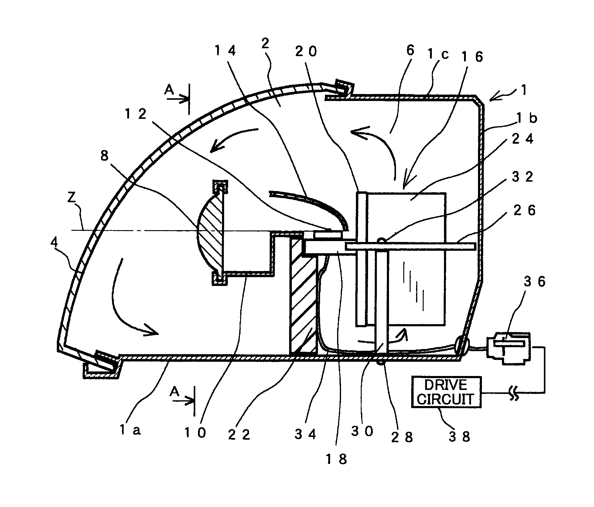
[0062]A description will now be given of the headlamp assembly according to the first embodiment of the present invention with reference to FIG. 1 to FIG. 3.

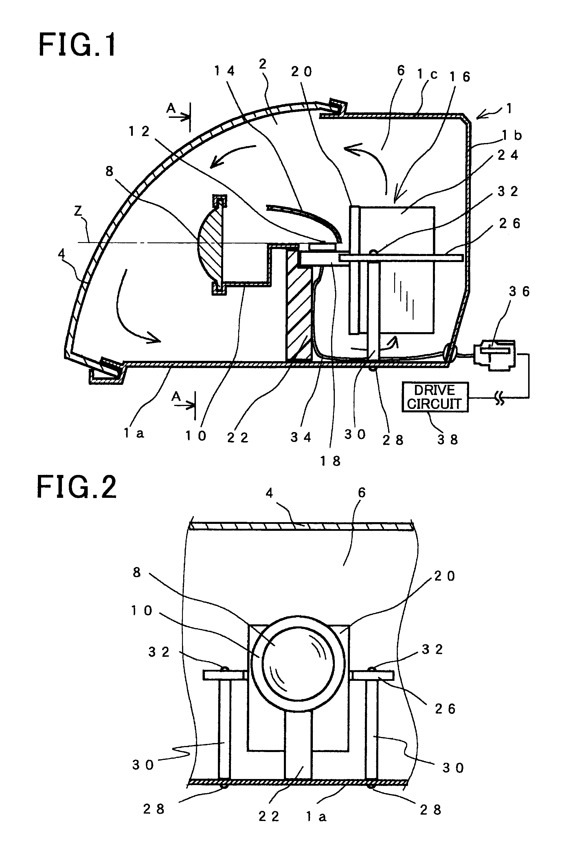
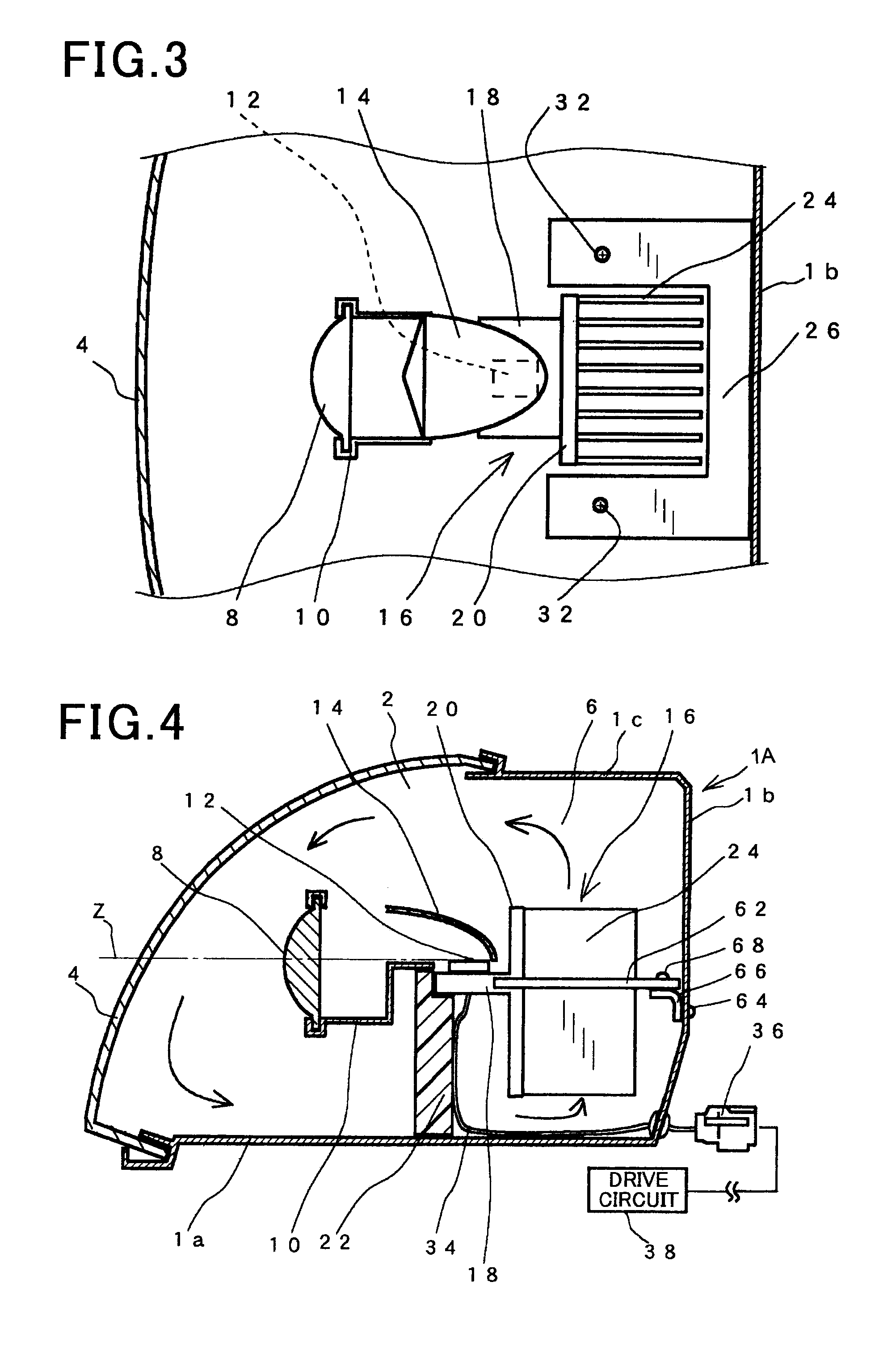
[0063]FIG. 1 is a schematic view showing a vertical cross section of the headlamp assembly (or a headlamp unit) which is mounted onto a vehicle (not shown) according to the first embodiment. FIG. 2 is a view showing a cross section of the headlamp assembly along the A-A line shown in FIG. 1. FIG. 3 is a schematic view showing a lateral cross section of the headlamp assembly according to the first embodiment shown in FIG. 1.

[0064]As shown in FIG. 1, the headlamp assembly according to the first embodiment is comprised of a housing case 1, a front lens cover 4 and other various types of components. A front part 2 of the housing case 1 is open. The front lens cover 4 is fitted and fixed to the front part 2 of the housing case1 in order to approximately close the inside of the housing case 1. That is, the housing case 1 and the front...

second embodiment

[0101]A description will be given of the headlamp assembly according to the second embodiment of the present invention with reference to FIG. 4 and FIG. 5.

[0102]FIG. 4 is a schematic view showing a vertical cross section of the headlamp assembly mounted to a vehicle according to the second embodiment of the present invention. FIG. 5 is a schematic view showing a lateral cross section of the headlamp assembly according to the second embodiment shown in FIG. 4.

[0103]The same components of the headlamp assemblies according to the first and second embodiments shown in FIG. 1 to FIG. 5 will be referred with the same reference numbers and the explanation of them is omitted for brevity.

[0104]The headlamp assembly according to the second embodiment has a control plate 62. The control plate 62 shown in FIG. 4 has the same shape of the control plate 26 of the first embodiment shown in FIG. 1. In the headlamp assembly according to the second embodiment, L-type brackets are fixed to the rear wa...

third embodiment

[0106]A description will be given of the headlamp assembly according to the third embodiment of the present invention with reference to FIG. 6, FIG. 7 and FIG. 8.

[0107]FIG. 6 is a schematic view showing a vertical cross section of a headlamp assembly mounted to a vehicle according to the third embodiment of the present invention. FIG. 7 is a view showing a cross section of the headlamp assembly along the B-B line shown in FIG. 6. FIG. 8 is a schematic view showing a lateral cross section of the headlamp assembly according to the third embodiment shown in FIG. 7.

[0108]The headlamp assembly according to the third embodiment has a control plate 40. In contrast with the shape of the control plate 20 shown in FIG. 1, the front part of the control plate 40 is bended toward the bottom wall 1a of the housing case 1B and extended at the front side of the vertical plate 20 shown in FIG. 6.

[0109]The control plate 40 in the headlamp assembly according to the third embodiment is fixed to the ver...


PUM


Abstract

A vehicle headlamp assembly including a housing case and a lens cover forming a light chamber, a projection lens, a shade and a light source are arranged within the light chamber in that order along an optical axis of the headlamp assembly. A radiating member includes plate-shaped radiating fins vertically placed in the light chamber, for radiating heat energy generated by the light source to surrounding air. A plate is arranged at a right angle to the radiating fins in the light chamber, for controlling air-convection flow around the radiating fins.

Description

CROSS-REFERENCE TO RELATED APPLICATION[0001]This application is related to and claims priority from Japanese Patent Application No. 2010-82209 filed on Mar. 31, 2010, the contents of which are hereby incorporated by reference.BACKGROUND OF THE INVENTION[0002]1. Field of the Invention[0003]The present invention relates to headlamp assemblies for motor vehicles, equipped with one or more radiating members capable of radiating heat energy generated by one or more light sources.[0004]2. Description of the Related Art[0005]There are various types of headlamp assemblies mounted to motor vehicles equipped with light emitting diodes. For example, Japanese patent No. JP4289268 has disclosed such a headlamp assembly comprised of a headlamp and a light emitting diode. In the headlamp assembly, a light projection lens, a shade and a light source are arranged in order, and a reflector is arranged so that it faces the light source. The reflector reflects the light generated by the light source to...

Claims


Application Information

Patent Timeline
Patent Type & Authority Patents(United States)
IPC IPC(8): B60Q1/04
CPCF21S48/328F21S48/1159F21S48/321F21S45/49F21S45/47F21S45/60F21S45/48F21S41/148F21S45/435
Inventor TOMINAGA, MOTONORINISHITANI, DAISUKENAKANO, TAKAHIRO
Owner NIPPON SOKEN
Why Eureka
Try Eureka