Coupling guard

Active Publication Date: 2009-10-22
LABARGE III WILLIAM E
View PDF3 Cites 23 Cited by
  • Summary
  • Abstract
  • Description
  • Claims
  • Application Information

AI Technical Summary

Benefits of technology

[0004]The present guard is adapted to encompass a coupling joint, but is adjustable in height and length to accommodate height and length variations of couplings often seen on job sites. Further, it includes relatively few major components, several of which are duplicates, thus reducing complexity and providing an arrangement t

Problems solved by technology

Another problem is that complex guards and/or difficult-to-install guards are soon removed from (or left off from) machinery because maintenance personnel and workers get tired of trying to work around them.
One practical reason that guards become complex or expensive is because of the tendency to custom manufacture guards for each app

Method used


Image

  • Coupling guard
  • Coupling guard
  • Coupling guard

Examples


Embodiment Construction

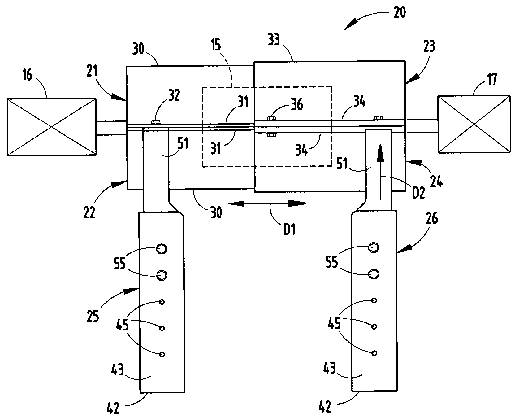
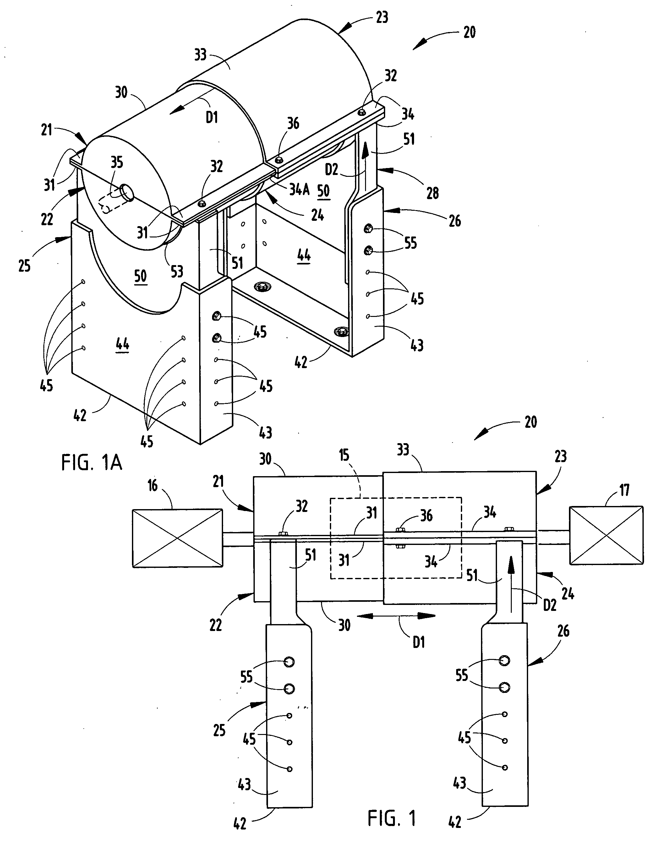
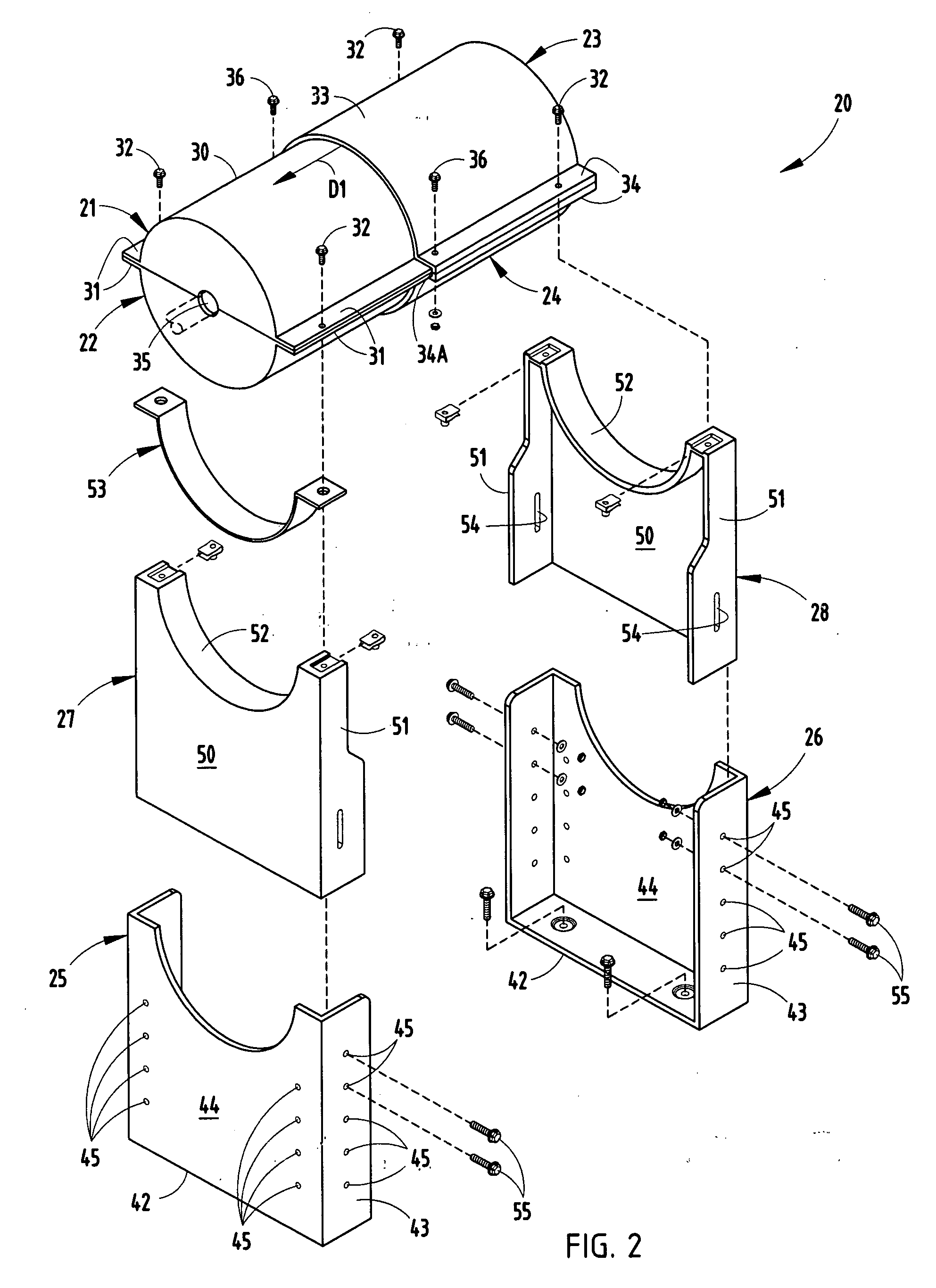
[0018]A guard assembly 20 (FIGS. 1-2) is provided for covering a rotating power coupling joint 15 such as for transmitting power between the shaft of a motor 16 and the shaft of a pump or gear box 17. The guard assembly 20 includes a first pair of opposing clamshell covers 21 / 22, a second pair of opposing clamshell covers 23 / 24, a pair of main supports 25 / 26, and a pair of adjustable brackets 27 / 28. The covers 21 / 22 are identical in shape and include bodies 30 defining a semi-cylindrical chamber and lateral flanges 31. When positioned together, the lateral flanges 31 abut on each side, and their bodies 30 define a cylindrical housing with a relatively small opening 35 for the shaft at one end and an oppositely-facing large open end. Flanges 31 are attached together along overlapping portions, such as by screws or bolts 32. The covers 23 / 24 are also identical in shape and include bodies 33 defining a semi-cylindrical chamber and lateral flanges 34. When positioned together, their lat...


PUM


Abstract

A guard for shielding a coupling joint joining rotating shafts includes first and second cylindrical components configured to telescopingly adjustably engage to enclose the coupling joint. The cylindrical components are made from opposing identical semi-cylindrical cover halves, each with lateral flanges, with one set of lateral flanges forming an inwardly-facing longitudinal slot for slidably receiving the other pair of lateral flanges. A fastener extended through overlapping flanges fixes the length adjustment. A pair of supports includes a vertically adjustable bracket on spaced stands, the brackets being configured to wedgingly engage the supports when secured in a vertically adjusted position thereon. The cover halves, supports and brackets can be thermoformed from heat.

Description

[0001]This application claims benefit under 35 U.S. C. §119(e) of provisional application Ser. No. 61 / 045,384, filed Apr. 16, 2008, entitled COUPLING GUARD, the entire contents of which are incorporated herein.BACKGROUND[0002]The present invention relates to guards for covering coupling joints that connect rotating shafts on machinery.[0003]Guards are often used to cover coupling joints in order to prevent accidental contact with fast rotating coupling joints, such as for covering coupling joints connecting motors to machinery for power transmissions. Further, many standards require guards, such as standards by OSHA, ASME and ANSI organizations. However, guards must not only prevent accidental contact, they also must be quickly removable to allow efficient repair. Also, guards must preferably be low cost for competitive reasons. Another problem is that complex guards and / or difficult-to-install guards are soon removed from (or left off from) machinery because maintenance personnel a...

Claims


Application Information

Patent Timeline
IPC IPC(8): F16D3/84F16P1/00
CPCF16D3/841Y10T74/2193F16P1/02
Inventor LABARGE, III, WILLIAM E.
Owner LABARGE III WILLIAM E
Why Eureka
Try Eureka