Cleaning appliance

Active Publication Date: 2009-10-29
DYSON TECH LTD
View PDF10 Cites 95 Cited by
  • Summary
  • Abstract
  • Description
  • Claims
  • Application Information

AI Technical Summary

Benefits of technology

[0008]Preferably, the separating apparatus is located between the suction conduit and the elongate handle. This arrangement improves the weight balance of the hand-held vacuum cleaner

Problems solved by technology

This may result in the hand-held vacuum cleaner described above being tiring and uncomfortable to use because the

Method used


Image

  • Cleaning appliance
  • Cleaning appliance
  • Cleaning appliance

Examples


Embodiment Construction

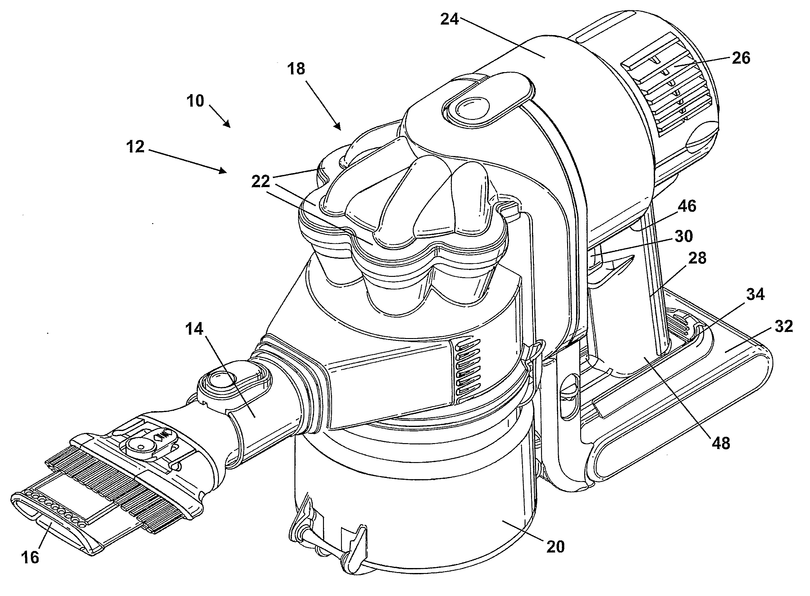
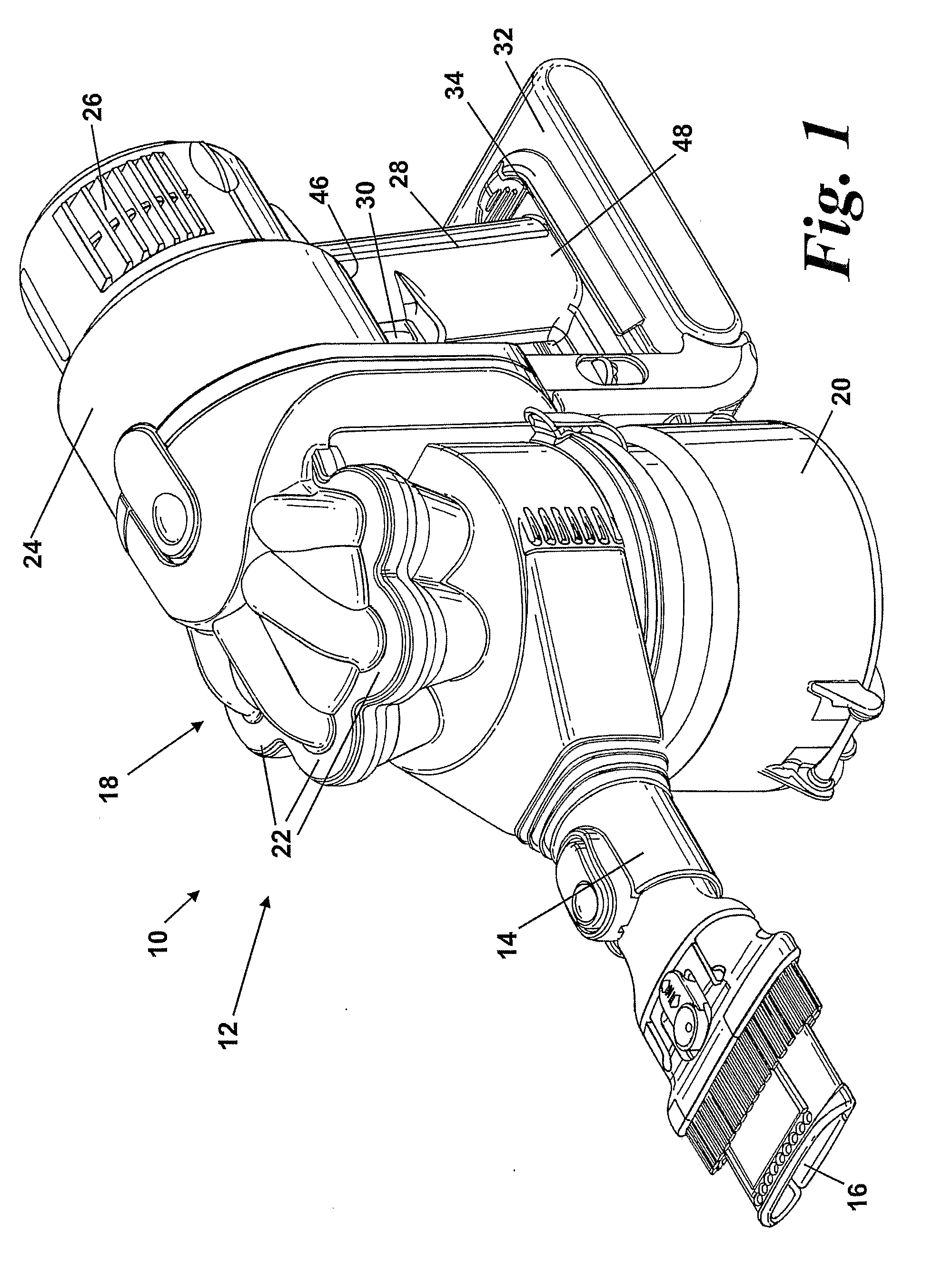
[0014]FIG. 1 shows a hand-held vacuum cleaner 10. The hand-held vacuum cleaner 10 comprises a main body 12. The main body 12 includes a suction conduit 14 having a suction opening 16. The main body 12 also includes cyclonic separating apparatus 18 for separating dirt and dust from an airflow drawn in through the suction opening 16. The cyclonic separating apparatus 18 is in communication with the suction conduit 14 and the suction opening 16. The cyclonic separating apparatus 18 comprises an upstream cyclone 20 and a plurality of downstream cyclones 22 but further detail is not material to the invention and therefore will not be described.

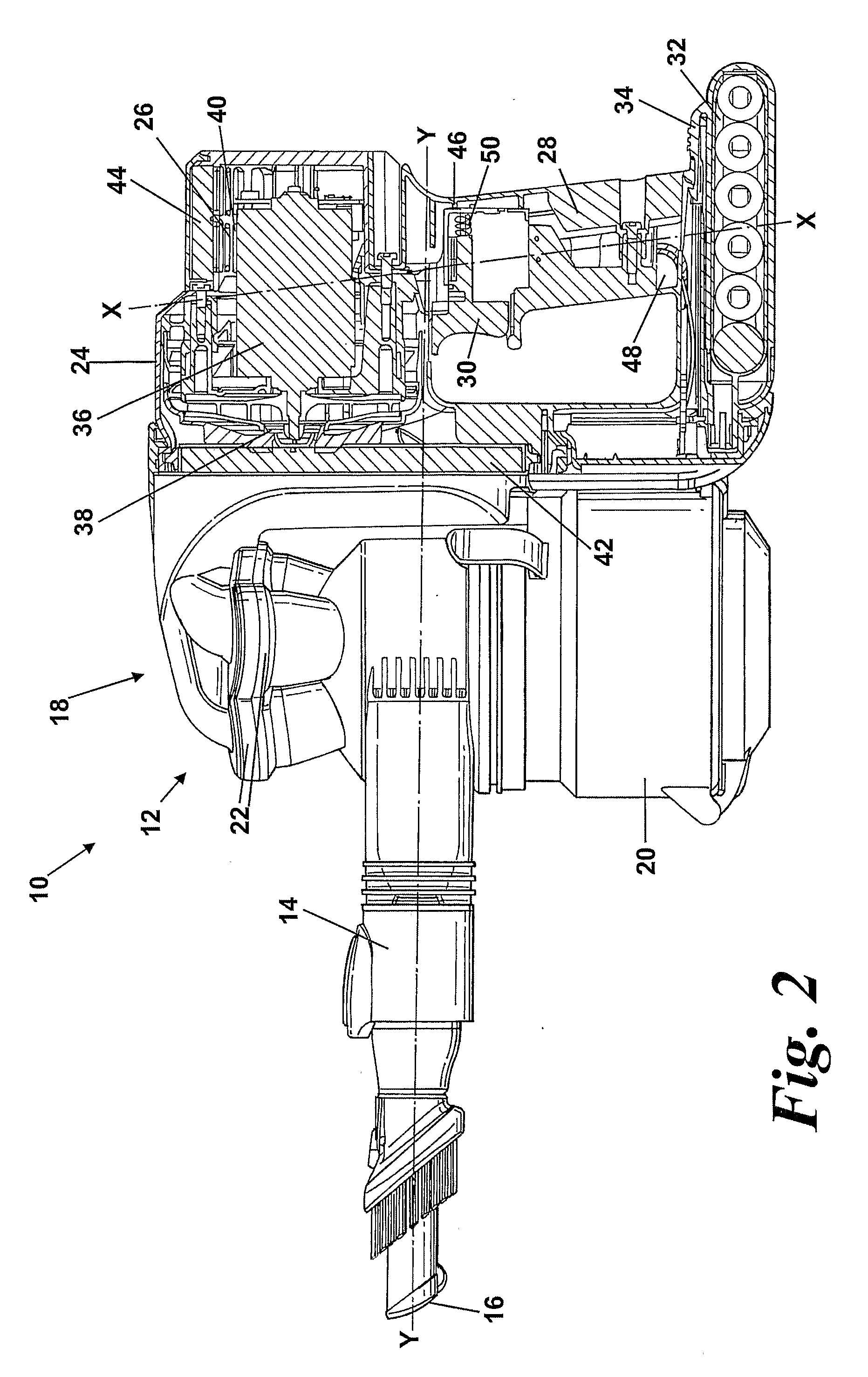
[0015]The main body 12 further includes a motor housing 24 having a plurality of exhaust vents 26 formed therein. A flowpath extends from the suction opening 16, through the suction conduit 14, the cyclonic separating apparatus 18 and the motor housing 24 to the exhaust vents 26. A handgrip 28 is located below the motor housing 24 for manipulating ...


PUM


Abstract

A hand-held cleaning appliance includes a suction conduit having a longitudinal axis, an airflow generator generating an airflow along the suction conduit, a separating apparatus arranged in communication with the suction conduit for separating dirt and dust from the airflow, a power source supplying power to the airflow generator and an elongate handle disposed between the airflow generator and the power source. The elongate handle is dimensioned and arranged to be gripped by a user's hand and the elongate handle lies transverse to the longitudinal axis of the suction conduit. By providing a hand-held vacuum cleaner with such an arrangement, the hand-held vacuum cleaner is easier and more comfortable to manipulate in use.

Description

REFERENCE TO RELATED APPLICATIONS[0001]This application is a national stage application under 35 USC 371 of International Application No. PCT / GB2007 / 002536, filed Jul. 6, 2007, which claims the priority of United Kingdom Application No. 0614235.0, filed July 18, 2006, the contents of which prior applications are incorporated herein by reference.FIELD OF THE INVENTION[0002]The invention relates to a hand-held cleaning appliance. More particularly, the invention relates to a hand-held vacuum cleaner.BACKGROUND OF THE INVENTION[0003]Hand-held vacuum cleaners are known from, for example, GB 1 207 278. This document discloses a hand-held vacuum cleaner having an elongate main body with an air inlet, a suction conduit and a dust bag for separating dirt and dust from an airflow. A motor and fan assembly is provided in the main body together with a power source. A handgrip is located on the upper part of the hand-held vacuum cleaner. The handgrip extends parallel to the elongate main body a...

Claims


Application Information

Patent Timeline
IPC IPC(8): A47L5/24
CPCA47L5/24A47L9/22A47L9/322A47L9/2884A47L9/2857A47L9/16A47L9/28A47L9/32
Inventor DYSON, JAMESHICKMOTT, RICHARD MORGANGAMMACK, PETER DAVID
Owner DYSON TECH LTD
Why Eureka
Try Eureka