
Magnetic Organizer

Inactive Publication Date: 2009-10-29
PENN UNITED TECH
View PDF20 Cites 10 Cited by
  • Summary
  • Abstract
  • Description
  • Claims
  • Application Information

AI Technical Summary

Benefits of technology

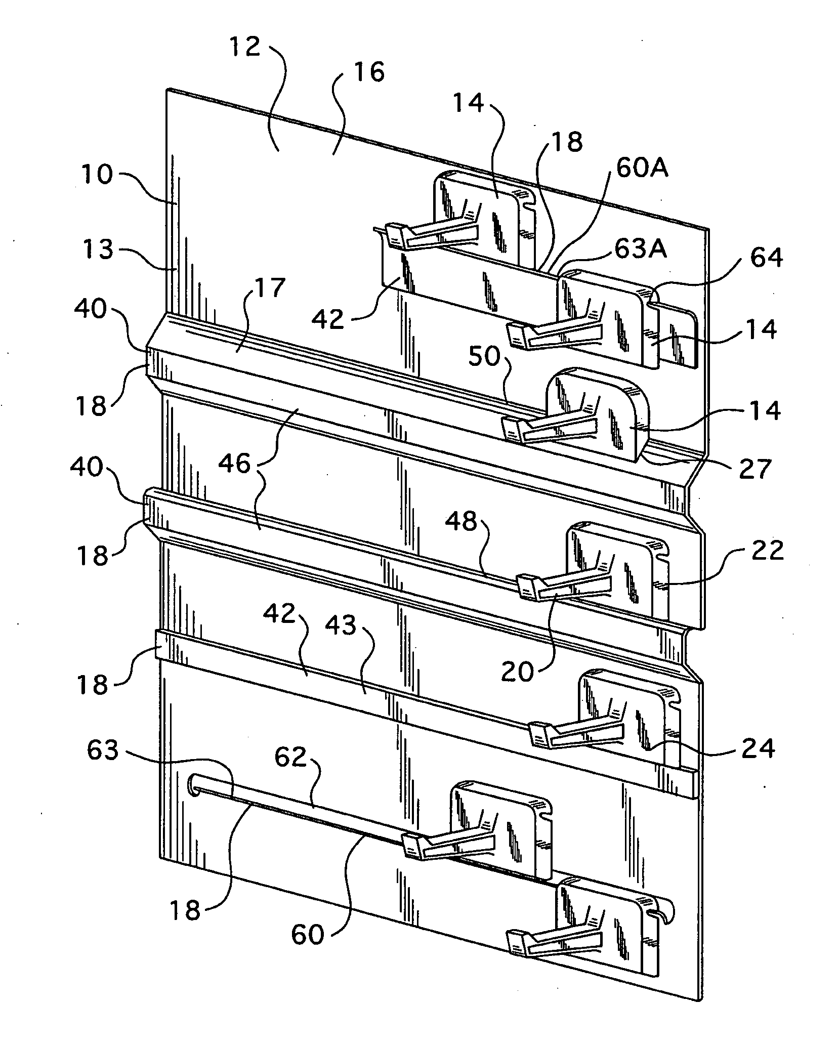
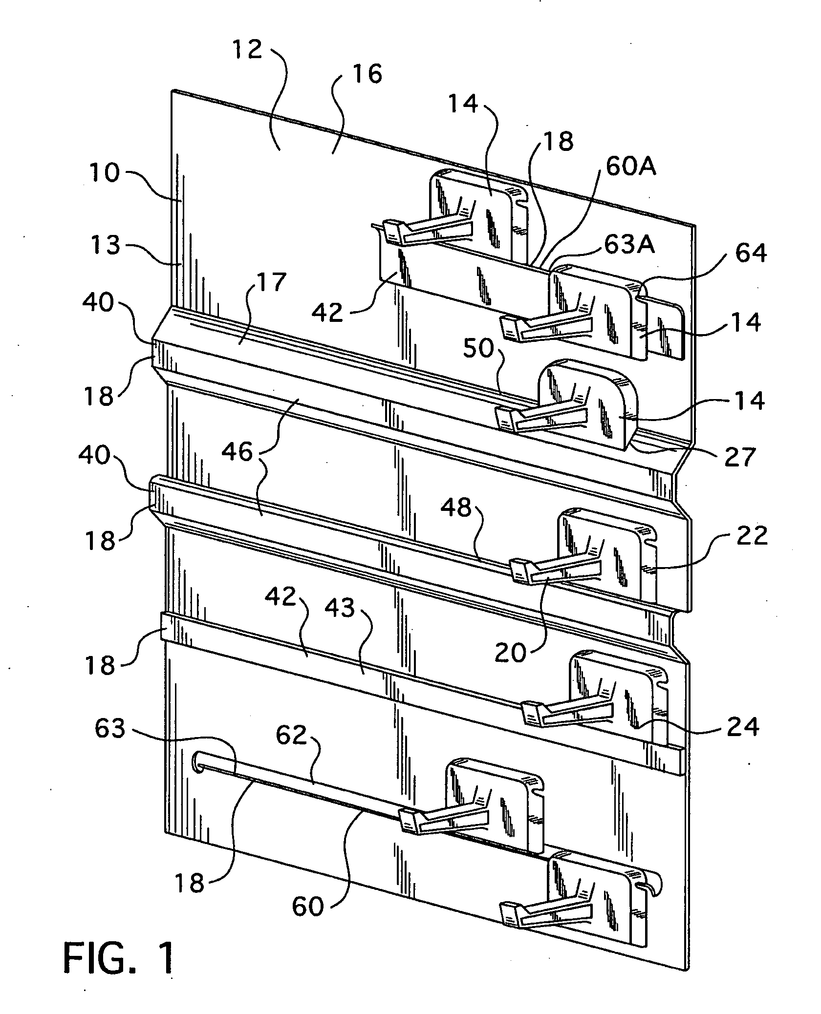
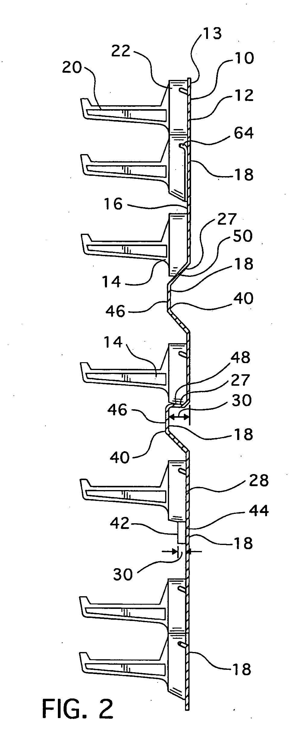
[0010]The present invention overcomes this problem by providing cooperative magnetic members, one generally planar member, and at least one support assembly having a magnetic member, and including one or more horizontally-extending protuberances on the generally planar member. The protuberances create a non-vertical surface that at least some portion of the support assemblies may catch upon, thereby preventing downward sliding.
[0011]It is noted that any two objects placed in contact with each other have a “starting friction” that must be overcome prior to the two objects sliding against each other. Once objects are in motion, a “sliding friction” exists therebetween. The force required to overcome the starting friction is always higher than the force required to overcome the sliding friction. Typically, both the starting friction and the sliding friction may be increased by increasing the coarseness of the two objects. For example, it is easier to slide two sheets of plain paper against each other than it is to slide two pieces of sandpaper against each other. Further, starting friction is increased and therefore the force required to overcome the starting friction is increased, when the objects are biased or pressed together. Again, using sheets of paper as an example, if one person was to hold three sheets of paper between their thumb and forefinger and apply minimal force, another person could remove the middle sheet of paper with ease. This is because there is a minimal starting friction between the sheets of paper; however, if the person holding the paper were to greatly increase the force applied by their thumb and forefinger, the person removing the middle sheet would have to pull harder as the starting friction is greatly increased.
[0012]The strength of a magnetic attraction relates to both the strength of the magnet and the distance to the ferrous object. Further, even a slight increase in distance between the magnet and the object will greatly reduce the strength of the magnetic attraction. Thus, when coupling two objects by magnetic attraction, it is best to have as much of the surface of the two magnetically attracted objects as close together as possible, and more preferably in contact with each other. Accordingly, most magnets and the surface to which they are attached are smooth, thereby increasing the surface area in contact; but, as noted above, smooth surfaces tend to have a lower starting / sliding friction. Thus, while an increased magnetic force acts to increase the starting friction, that is, the magnetic force is similar to pressing the magnet against the surface, this increase in starting friction is not always so great as to prevent the magnet from sliding on a ferrous surface. This is especially true as the inclination of the surface becomes more vertical and / or the weight of the magnet, or any object the magnet supports, increases.

Problems solved by technology

This is because there is a minimal starting friction between the sheets of paper; however, if the person holding the paper were to greatly increase the force applied by their thumb and forefinger, the person removing the middle sheet would have to pull harder as the starting friction is greatly increased.
Further, even a slight increase in distance between the magnet and the object will greatly reduce the strength of the magnetic attraction.
That is, as noted above, many magnetic devices have a sufficient strength to support the weight of a tool, i.e., the magnet device will not detach from a ferrous surface due to the weight of the tool, but not enough strength to prevent sliding on a vertical surface.

Method used


Image

  • Magnetic Organizer
  • Magnetic Organizer
  • Magnetic Organizer

Examples


Embodiment Construction

[0029]As used herein, “generally planar” is used in a broad sense meaning an object having a thickness that is substantially smaller than the object's length and / or width and which generally defines a plane. It is specifically noted that “generally planar” does not mean substantially flat as one object of this invention is to provide a “generally planar” member having protuberances on an attachment surface.

[0030]As used herein, a “magnetic member” is either a member that is attracted to iron or steel, e.g., a typical magnet, or an iron or steel member to which a magnet is attracted. Further, when two “magnetic members” are identified as “cooperative,” it means that at least one magnetic member is attracted to iron or steel. That is, for example, two steel members may each be “magnetic members,” but are not “cooperative magnetic members” as neither member would be attracted to the other.

[0031]As shown in FIGS. 1 and 2, a magnetic organizer 10 includes a generally planar magnetic memb...


PUM


Abstract

A magnetic organizer is provided that includes cooperative magnetic members, one generally planar member and one support assembly having a magnetic member, and including one or more horizontally-extending protuberances on the generally planar member. The protuberance is a double taper ridge and the support assembly includes a clamp assembly structured to engaged the double taper ridge in a clamping manner.

Description

CROSS REFERENCE TO RELATED APPLICATION [0001]This application claims priority under 35 U.S.C. §119(e) to U.S. Traditional patent application Ser. No. 12 / 109,015, filed Apr. 24, 2008, entitled MAGNETIC ORGANIZER.BACKGROUND OF THE INVENTION[0002]1. Field of the Invention[0003]This invention relates to a vertical, panel-like organizer structured to have movable supports coupled thereto, and more specifically, to a magnetic organizer having a generally planar magnetic member with movable support assemblies coupled thereto, the generally planar magnetic member has at least one horizontally extending protuberance on an attachment surface. Further, the support assemblies are structured to include a clamp assembly that engages the at least one horizontally extending protuberance in a clamping manner.[0004]2. Background Information[0005]Vertical organizers are devices structured to support various items along a vertical surface. Of course, vertical organizers require an attaching means struc...

Claims


Application Information

Patent Timeline
IPC IPC(8): F16M11/00
CPCA47B96/061A47F5/0853A47B96/07A47B96/067
Inventor PHILLIPS, SR., CHARLES M.NOAH, MARK P.
Owner PENN UNITED TECH
Learn More