Linear drive ultrasonic motor

a technology of ultrasonic motors and ultrasonic motors, applied in piezoelectric/electrostrictive/magnetostrictive devices, piezoelectric/electrostriction/magnetostriction machines, electrical equipment, etc., can solve the problems of insufficient protection of the contents of the case, inability to fix the side of the pressing spring, external apparatus, etc., and achieve stable pressing force and less restrictions on a relationship

Inactive Publication Date: 2009-10-29
OLYMPUS CORP
View PDF5 Cites 2 Cited by
  • Summary
  • Abstract
  • Description
  • Claims
  • Application Information

AI Technical Summary

Benefits of technology

[0008]The present invention is made in view of the abovementioned circumstances, and an object of the present invention is to provide a small-size linear drive ultrasonic motor which is capable of achieving a stable pressing force, and which has fewer restrictions regarding a relationship with an external apparatus. Moreover, an object of the present invention is to provide a linear drive ultrasonic motor in which it is possible to protect assuredly the contents of a case member.

Problems solved by technology

Furthermore, for generating sufficient pressing force such that the mobile object 904 can be moved, it is not possible to fix a side of the pressing spring 905 to the external apparatus.
As the side of the pressing spring 905 cannot be fixed, the protection of the contents of the case 906 has not been sufficient.

Method used


Image

  • Linear drive ultrasonic motor
  • Linear drive ultrasonic motor
  • Linear drive ultrasonic motor

Examples


Embodiment Construction

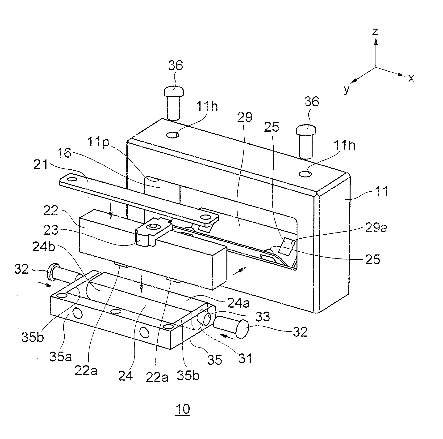
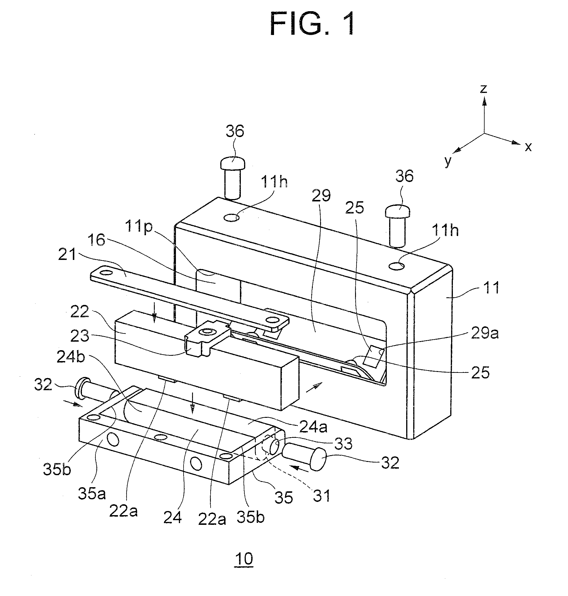
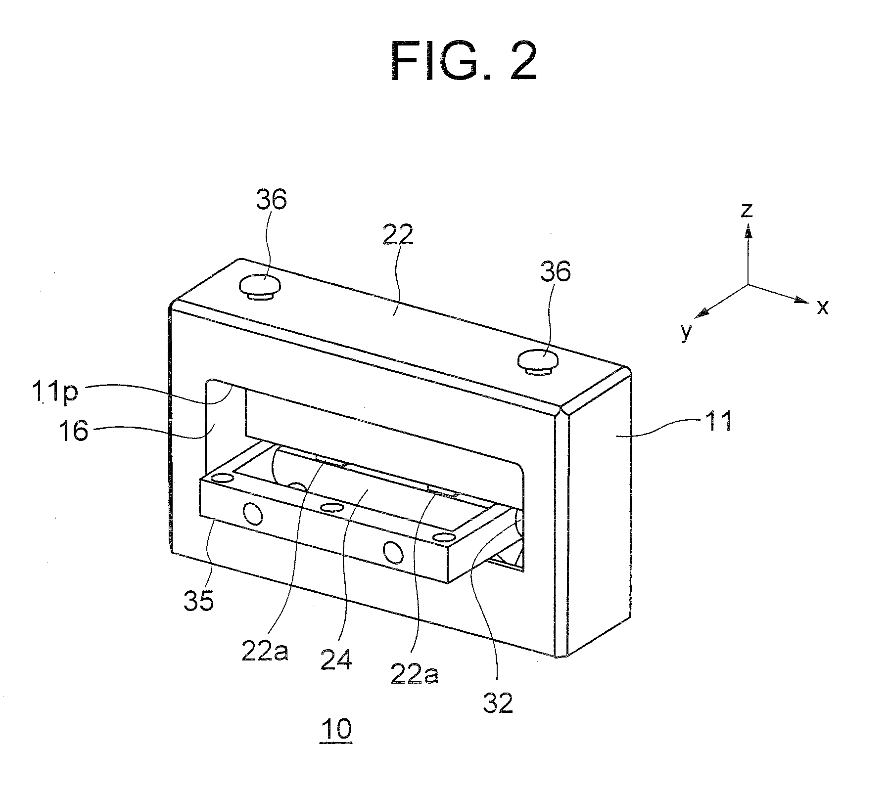
[0021]An ultrasonic motor 10 (linear drive ultrasonic motor) according to an embodiment of the present invention will be described below while referring to FIG. 1 and FIG. 2. However, the present invention is not restricted by the embodiment described below. Here, FIG. 1 is an exploded perspective view showing a structure of the ultrasonic motor 10, and FIG. 2 is a perspective view showing an outward appearance of the ultrasonic motor 10 in an assembled state.

[0022]As shown in FIG. 1, the ultrasonic motor 10 includes a vibrator 22 as an ultrasonic vibrator, a driven member 24, a pressing member 21, a case member 11, and rolling members 25. Each member will be described below in detail.

[0023]Both the vibrator 22 and the case member 11 have a substantially rectangular parallelepiped outer shape, and an accommodating recess 16 is formed at an interior of the case member 11. The pressing member 21, the vibrator 22, a guiding member 29, and the rolling members 25 are accommodated in the ...


PUM


Abstract

A linear drive ultrasonic motor includes at least an ultrasonic vibrator having a piezoelectric element, a driven member which is driven by a frictional force between the driven member and the ultrasonic vibrator, a pressing member which presses the ultrasonic vibrator such that a frictional force is generated between the ultrasonic vibrator and the driven member, a case member which accommodates the ultrasonic vibrator, the pressing member, and the driven member, and a coupling member which is coupled with the driven member at an interior of the case member. The case member includes an opening portion for allowing a part of the coupling member to pass through.

Description

CROSS-REFERENCE TO RELATED APPLICATION[0001]The present application is based upon and claims the benefit of priority from the prior Japanese Patent Application No. 2008-114301 filed on Apr. 24, 2008; the entire contents of which are incorporated herein by reference.BACKGROUND OF THE INVENTION[0002]1. Field of the Invention[0003]The present invention relates to a linear drive ultrasonic motor[0004]2. Description of the Related Art[0005]A vibration apparatus in Japanese Patent No. 3524248 Specification (FIG. 3A and FIG. 3B) can be cited as an example of a conventional linear drive ultrasonic motor. Here, FIG. 3A and FIG. 3B are diagrams showing a structure of the conventional linear drive ultrasonic motor, where FIG. 3A is an exploded perspective view and FIG. 3B is a vertical cross-sectional view.[0006]The vibration apparatus shown in FIG. 3A and FIG. 3B includes a case 906 which accommodates a vibrating body 901, a mobile object 904 which passes through the case 906 and makes a cont...

Claims


Application Information

Patent Timeline
Patent Type & Authority Applications(United States)
IPC IPC(8): H02N2/04
CPCH02N2/04H02N2/026
Inventor TAKIZAWA, HIROYUKI
Owner OLYMPUS CORP
Why Eureka
Try Eureka