
Magnetic Mat for Holding Surgical Instruments

a technology for surgical instruments and magnetic mats, applied in the surface field, can solve the problems of unusable surgical procedures, unnecessarily delayed surgical procedures, and the addition of additional instruments to the overall cost of the procedure, and achieve the effect of convenient disassembly

Inactive Publication Date: 2009-10-29
BASKETT MICHAEL D
View PDF20 Cites 29 Cited by
  • Summary
  • Abstract
  • Description
  • Claims
  • Application Information

AI Technical Summary

Benefits of technology

[0015]The present disclosure provides solutions to needs in the art by providing an expandable magnetic mat for holding surgical instruments wherein the overall size of the mat may be advantageously adjusted e.g., to account for patient size. Additionally, the mat of the present disclosure includes a plurality of magnet holders for holding magnets such that the magnets may advantageously be inserted, removed, replaced and / or exchanged. Furthermore, the mat of the present disclosure includes a plurality of links for connecting the magnet holders in a manner that the mat may be easily disassembled after use and portions thereof individually sterilized or replaced as needed. Additionally, the mat may be used alone or alternatively under, or over, a standard surgical drape.
[0017]According to another aspect, a kit for a magnetic mat is disclosed, the kit comprising: a plurality of magnet holders, each magnet holder having a space for receiving a magnet; a plurality of magnets; and a plurality of links, each link having first and second end portions configured to engage the magnet holders and connect the magnet holders together so as to form a two dimensional magnetic mat. The magnet holders and links may be comprised of e.g., stainless steel, plastic, rubber, or other conventional materials suitable for re-sterilization and / or the functions disclosed herein. Preferably, the magnet holders are capable of removably receiving magnets of different sizes and / or magnetic field strengths. In embodiments, the magnet holders include a plurality of peripheral notches, or troughs, that securely receive link end portions. In further embodiments, the magnet holders include an open cage structure for holding a magnet with minimal obstruction of its magnetic field.
[0018]According to yet another aspect, a magnetic mat for holding surgical instruments on a patient surface is disclosed, the mat comprising: a plurality of magnet holders, each magnet holder having a space for receiving a magnet; a plurality of magnets, each magnet disposed in a magnet holder; and means for connecting the magnet holders together so as to form a two dimensional magnetic mat. In one embodiment, the connecting means comprises a plurality of links. In other embodiments, the connecting means may be a sheet of material. The magnet holders and / or connecting means may be comprised of e.g., stainless steel, plastic, rubber, or other conventional materials suitable for re-sterilization and / or the functions disclosed herein. In embodiments, the magnet holders are capable of removably receiving magnets of different sizes and / or magnetic field strengths. In further embodiments, the magnet holders include an open cage structure for holding a magnet with minimal obstruction of its magnetic field.

Problems solved by technology

If an instrument does happen to fall, it becomes contaminated and therefore cannot be used again until re-sterilized.
As a result, the surgical procedure may be unnecessarily delayed until the contaminated instrument has been re-sterilized.
In some cases, another sterile instrument may be available, however introducing additional instruments typically adds to the overall cost of the procedure.
As a result of prolonging the procedure, the patient is placed at a higher risk of infection or other serious complications.
In addition, other surgeries may be subsequently delayed, and time wasted on the part of the surgeon and other hospital staff.
Unfortunately such designated areas may not be convenient for the surgeon and / or may become crowded by other instruments.
Moreover, magnets incorporated into the fabric of the drape tend to become compromised and / or break through the fabric of the drape as a result of repeat sterilization.
Such drapes require instruments to be placed in a designated tray which also may be inconvenient to the surgeon.
Additionally, such trays tend to become crowded with other instruments making it more difficult to access a particular instrument when needed quickly.
Moreover, if the instrument holder is not able to rest on a flat surface, it may rock or lie at a sloped angle causing instruments to slide.
Another significant drawback of conventional drapes is that the actual magnetic surface area is relatively small.
This is a particular problem concerning large or obese patients who tend to exhibit more curved or sloped surface areas when lying on an operating table.
As a result, instruments placed outside of the effective magnetic area of a drape will likely roll, slip, or otherwise fall, off of the patient surface.
Another problem associated with conventional magnetic drapes, as alluded to above, is that of sterilization.
Exposure to such high temperatures tends to reduce or compromise the attractive magnetic force.
Thus, repeat heat sterilization can have life-shortening effects on magnets.
In addition, because it is difficult to sterilize large drapes due to the size of the autoclave or sterilization device, such drapes tend to be small.
As a result, when these small drapes are used for larger or obese patients, surgical instruments are not able to be effectively retained on the patient surface.
Although disposable or single-use drapes can avoid some of the above mentioned sterilization problems, such drapes that incorporate magnets tend to be expensive.
To reduce costs, the number of magnets (and therefore the magnetic surface area) is kept relatively small—again leading to the above drawbacks associated with larger or obese patients.
Moreover, once these drapes have been used, both the drape and the magnets must be discarded, thereby wasting the magnets.

Method used


Image

  • Magnetic Mat for Holding Surgical Instruments
  • Magnetic Mat for Holding Surgical Instruments
  • Magnetic Mat for Holding Surgical Instruments

Examples


Embodiment Construction

[0026]Reference will now be made in detail to various exemplary embodiments of the invention, examples of which are illustrated in the accompanying drawings. The following detailed description is provided to supply a fuller description of certain embodiments of the invention, and is not intended as a limiting disclosure of all embodiments of the invention. Rather, those of skill in the art will be able to understand the full scope of the invention after consideration of the above broad description, the following detailed description of certain preferred embodiments, and the claims.

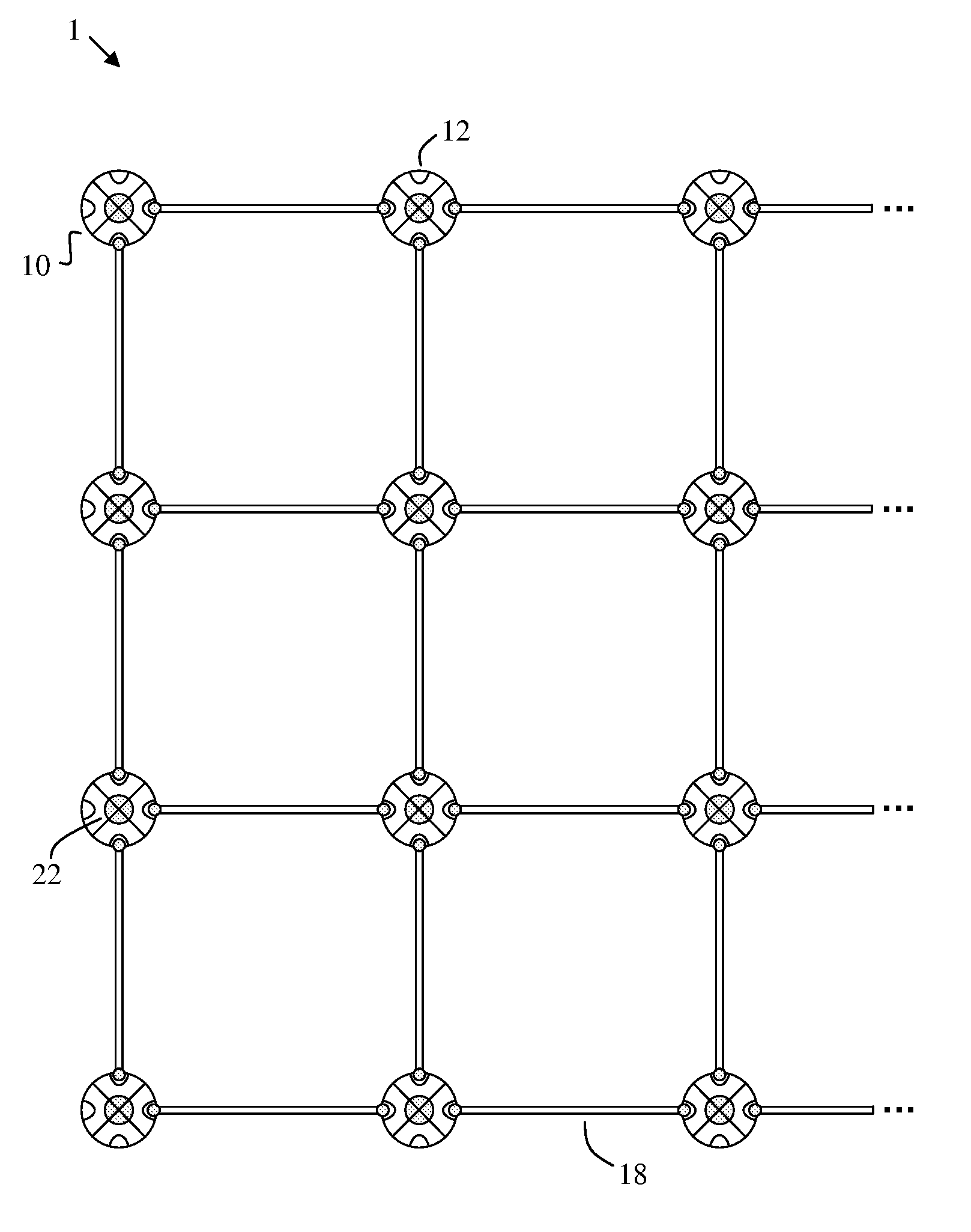
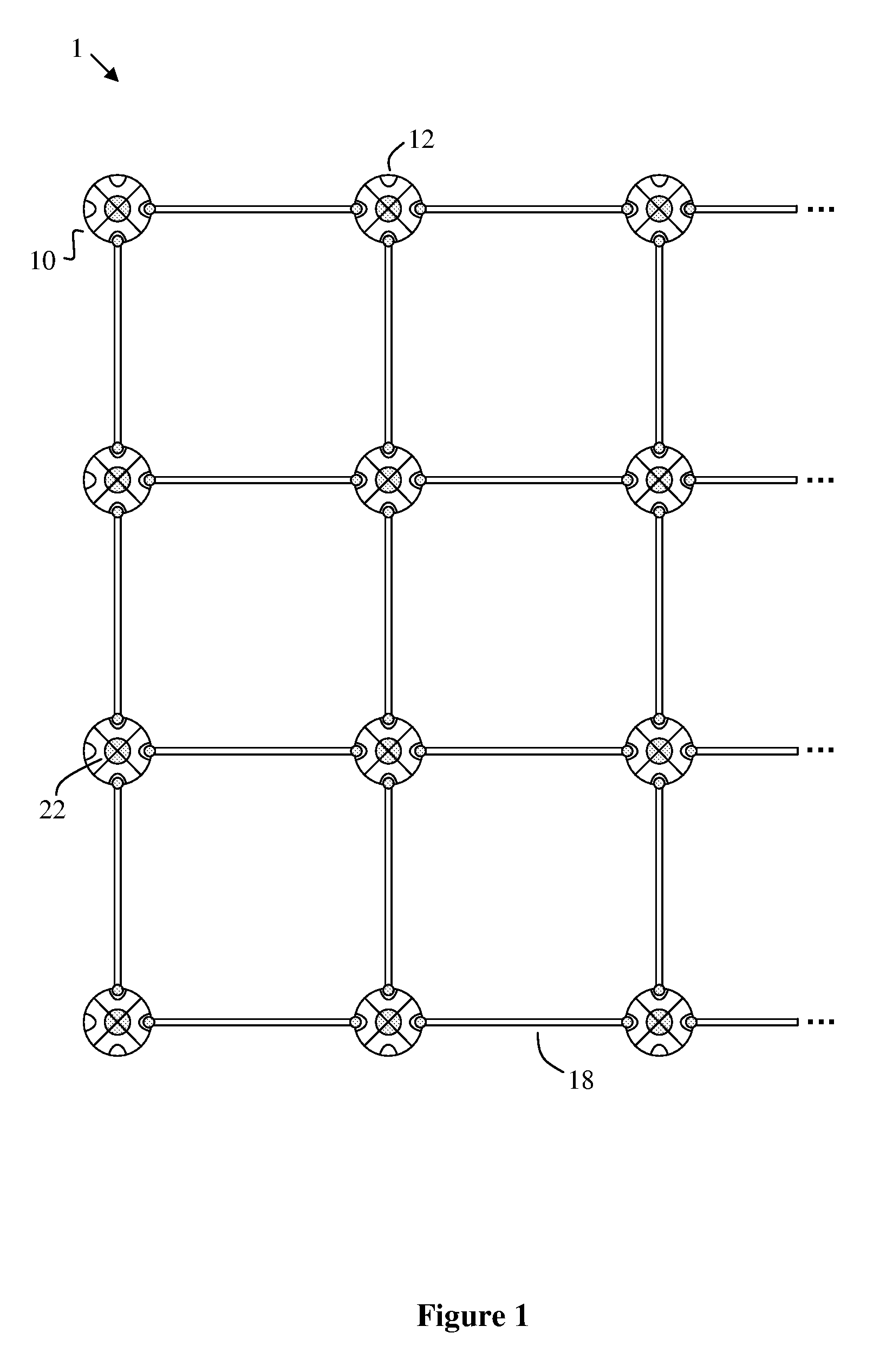
[0027]FIG. 1 depicts a magnetic mat 1 for holding metal surgical instruments on a patient surface. It is appreciated that the figure is meant to be illustrative and is not limited to the dimensions or configurations shown. In general, the mat 1 includes a plurality of magnet holders 10 for holding magnets 22 and a plurality of links 18 that connect the magnet holders 10 together in two dimensions. Preferab...


PUM


Abstract

A magnetic mat for holding surgical instruments. The mat includes a plurality of magnet holders configured to removably receive magnets therein. The magnet holders are connected together using a plurality of links so as to form a two dimensional mat adjustable in size. As a result, the effective magnetic surface area of the mat may be extended to provide adequate coverage for larger patients and thereby prevent instruments from falling off the patients' surface. In embodiments, the magnet holders may be opened such that different magnets may be inserted, removed, replaced and / or exchanged. Additionally, the magnet holders, links, and / or magnets may be independently sterilized, and / or replaced. In embodiments, the magnet holders include an open cage structure to hold a magnet with minimal obstruction of its magnetic field.

Description

BACKGROUND OF THE INVENTION[0001]1. Field of the Invention[0002]The present invention generally relates to a surface for retaining articles. More specifically, the present invention relates to a magnetic mat for holding surgical instruments.[0003]2. Description of Related Art[0004]It is common for surgical procedures to require many different surgical instruments such as scalpels, forceps, needles, sharps, scissors, clamps, etc. Typically, medical personnel will place instruments on the patient surface for easy access and to create a safe transfer zone. Such a hands-free practice reduces the risk of percutaneous injury to medical personnel as well as the possibility of dropping the instruments as a result of being passed back and forth.[0005]During the course of a procedure, it is highly important that surgical instruments do not fall to the floor. If an instrument does happen to fall, it becomes contaminated and therefore cannot be used again until re-sterilized. As a result, the s...

Claims


Application Information

Patent Timeline
IPC IPC(8): H01F7/20
CPCA61B19/10H01F7/0252A61B2019/0257A61B46/23A61B2050/21
Inventor BASKETT, MICHAEL D.
Owner BASKETT MICHAEL D
Learn More