Circuit for output voltage error detect and feedback in smps
a technology of output voltage and error detection, which is applied in the direction of power conversion systems, instruments, dc-dc conversion, etc., can solve the problems of deteriorating the stability of output voltage and increasing the cost of power circuits, so as to reduce the number of parts, simplify the power circuit, and reduce the cost
- Summary
- Abstract
- Description
- Claims
- Application Information
AI Technical Summary
Benefits of technology
Problems solved by technology
Method used
Image

Examples
first embodiment
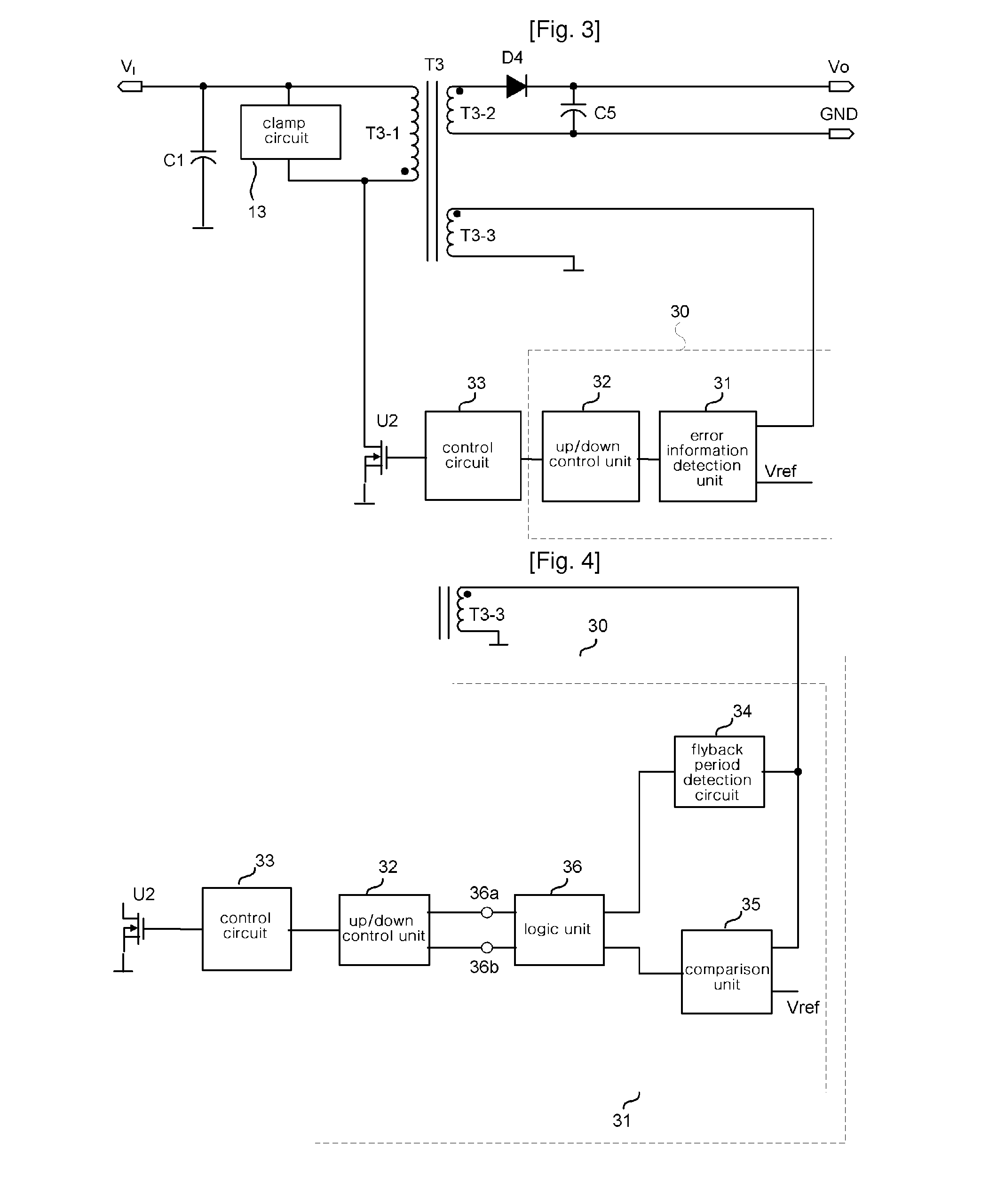
[0055]FIG. 4 is a diagram of a first embodiment showing the error information detection unit 31 of FIG. 3 in detail.
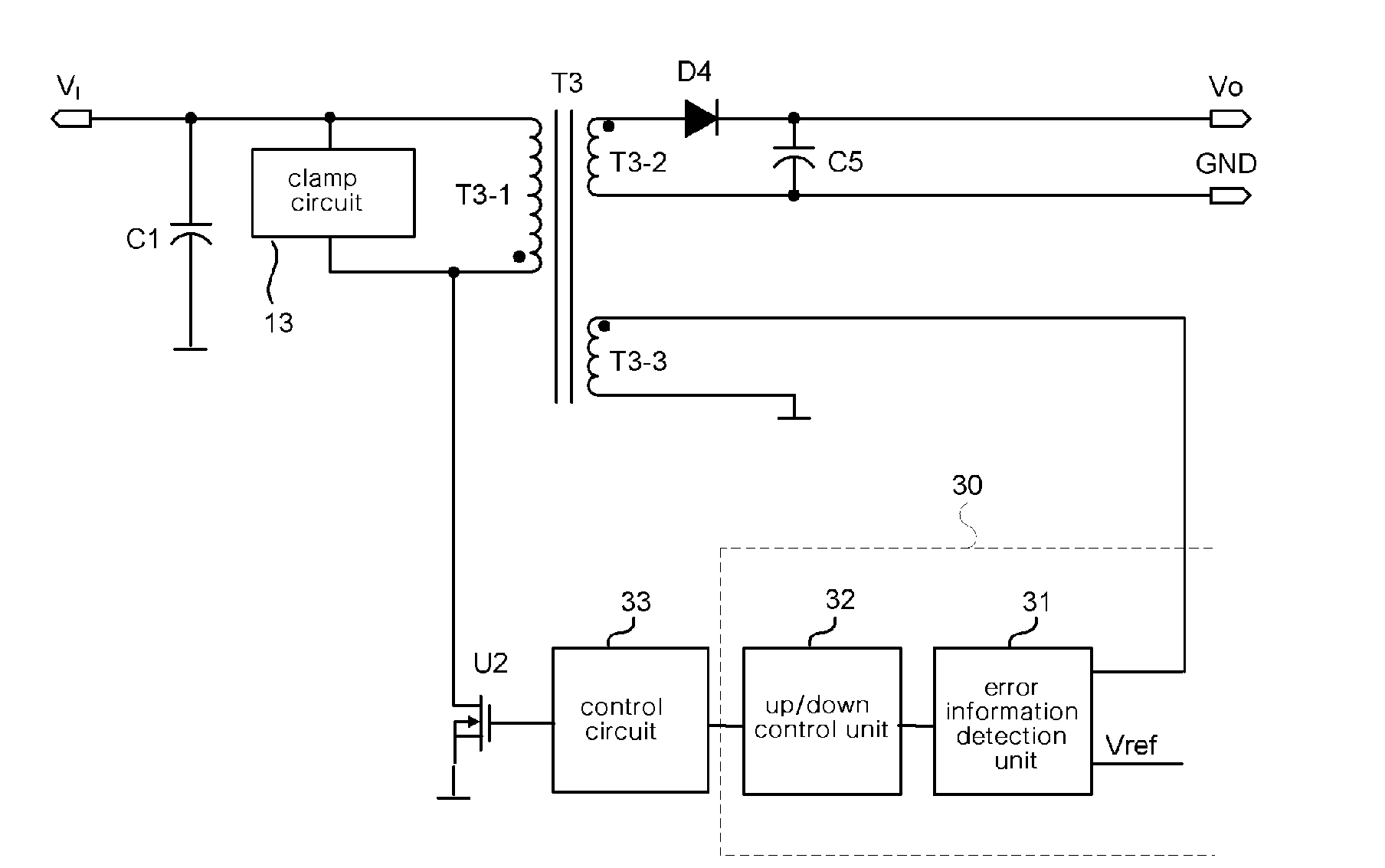
[0056]The error feedback circuit 30 according to the first embodiment includes an error information detection unit 31 for detecting the error information of an output voltage from voltage induced to a feedback winding T3-3, and an up / down control unit 32 for determining the amount of error from the output of the error information detection unit 31 and providing feedback corresponding to the determined amount of error.
[0057]The error information detection unit 31 includes a flyback period detection circuit 34 for detecting a flyback period from the voltage induced to the feedback winding T3-3, a comparison unit 35 for comparing the voltage induced to the feedback winding T3-3 with a reference voltage Vref, and a logic unit 36 for outputting the error information of the output voltage through a Vhigh output terminal 36a and a Vlow output terminal 36b according to the out...
third embodiment
[0099]FIG. 12 is a diagram of a third embodiment showing another construction of an error feedback circuit 60 according to the present invention and the detailed construction of the up / down control unit thereof.
[0100]The error feedback circuit 60 according to the third embodiment includes an error information detection unit 31′ for detecting the error information of an output voltage from a voltage induced to a feedback winding T3-3, and an up / down control unit 61 for determining the amount of error from the output of the error information detection unit 31′ and providing feedback corresponding to the amount of error.
[0101]The error information detection unit 31′ includes a flyback period detection circuit 34 for detecting a flyback period from the voltage induced to the feedback winding T3-3, a comparison unit 35 for comparing the voltage induced to the feedback winding T3-3 with a reference voltage Vref, and a switch 36′, the on / off operation of which is controlled by the flyback ...
fourth embodiment
[0107]FIG. 13 is a diagram of a fourth embodiment in which the location of the up / down control unit in the third embodiment of the error feedback circuit 60 according to the present invention, is changed.
[0108]FIG. 13 illustrates construction in which the location of the up / down control unit 61′ of FIG. 12 is moved to a location between a switch 36′ and a comparison unit 35, and the input circuit of the up / down control unit 61 is slightly simplified.
[0109]*The error feedback circuit 60 of FIG. 13 has a circuit structure that uses a single-output switch 36′ having three states, namely “H”, “open” and “L”. In this case, the amount of charge / discharge current of the up / down control unit 61′ is given by the output of the comparison unit 35. During the flyback period, the output of the flyback period detection circuit 34 is “H”, and the switch 36′ is closed, and thus enables the feedback condenser Cfb2 to be charged through the current source I1 of the up / down control unit 61′, or to be ...
PUM
 Abstract
Description
Claims
Application Information