Radio frequency amplifier and method of driving the same

a radio frequency amplifier and amplifier technology, applied in pulse manipulation, pulse technique, instruments, etc., can solve the problems of inability to enhance efficiency, and large noise of large-sized cooling water circulating devices, so as to reduce the efficiency of power amplifiers and high efficiency. , the effect of high efficiency

Inactive Publication Date: 2003-03-06
AGILENT TECH INC
View PDF2 Cites 18 Cited by
  • Summary
  • Abstract
  • Description
  • Claims
  • Application Information

AI Technical Summary

Benefits of technology

[0016] According to Invention I, such a problem that the efficiency of a radio frequency amplifier that has been employed up to now is solved by using a radio frequency amplifier including a pulse width control circuit that controls a pulse width upon receiving an output control signal and a power amplifier that is driven by the pulse width control circuit, that is, a D / E class power amplifier in an inductively coupled plasma mass spectrometer and an inductively coupled plasma optical or atomic emission spectrometer. The power supply application efficiency of the D / E class power amplifier is extremely high to the degree of 100% in theory, thereby being capable of downsizing and simplifying a power device and a cooling device for the radio frequency amplifier. In addition, the following unique effects can be indicated by the application of the present invention. That is, as unique improvements, in an unstable transitional output state when plasma is ignited where impedance matching is insufficient, it is hard to destroy the radio frequency amplifier, and it is easy to maintain an output until plasma is ignited, and also discharge is readily developed due to an increase in harmonic components, and the plasma is readily ignited for those reasons.
[0022] Invention III is the radio frequency amplifier as defined above as Invention II, characterized in that said variable wave height and variable wave width pulse wave generating circuit generates a control rectangular wave having a sufficient pulse height to saturate a power switching element used in a switching power amplifier and operates the power amplifier with a high efficiency through saturated operation of the switching element in the case where a high efficiency is required, and decreases the efficiency of the power amplifier through unsaturated operation of the switching element by a control input a lower pulse height in the case of a low output and where a relatively high efficiency is not required.
[0023] According to Invention III, in the variable wave height and variable wave width pulse wave generating circuit, the pulse height is controlled to conduct unsaturated operation so that the conductive resistance of the switching element increases. This operation is added to the pulse width control at the time of the low output, thereby being capable of solving the problem of the over-cooling because the heating necessary for the power loss in the conductive resistance of the switching element is obtained.
[0025] According to Invention IV, in the variable wave height and variable wave width pulse wave generating circuit, the output control according to the pulse height is added to the output control according to the pulse width, and the power consumption (power application efficiency) is set as a control parameter. The radio frequency amplifier operates in accordance with the input values of the output power and the power consumption (power application efficiency), which are set in advance, and the set input mainly uses the pulse width control to make the power application efficiency maximum at the time of the high output whereas the pulse height control is added so as to prevent the power application efficiency from being too high at the time of the low output, thereby being capable of solving problems such as the controllability and over-cooling at the time of the low output.
[0027] According to Invention V, in the variable wave height and variable wave width pulse wave generating circuit, the output control according to the pulse height is added to the output control according to the pulse width, and control is made to maintain the loss power constant. Control is so made as to provide the loss power set with the output power of a predetermined operation range. In this case, the load of the amplifier with respect to the cooling system becomes constant, and the excellent efficiency is obtained without worrying about over-cooling. Also, the controllability at the time of the low output is excellent.

Problems solved by technology

However, in case of the B-class operation, there arises such a problem that the efficiency cannot be enhanced so that the theoretical maximum efficiency is 78.5%.
In the case where the power amplifier is operated by, for example, an output of 1.6 kW, the efficiency is limited to about 60% in fact, and heat of 1 kW or less is generated in the amplifier.
A large-sized cooling water circulating device is large in noise, as a result of which because an expensive cooling water circulating device which is high in cooling capability is required and the cooling water circulating device is noisy, the cooling water circulating device may be located in another room in some cases.
In addition, a power supply capacity itself of the amplifier increases, resulting in an inhibition factor of downsizing of the entire device.

Method used


Image

  • Radio frequency amplifier and method of driving the same
  • Radio frequency amplifier and method of driving the same
  • Radio frequency amplifier and method of driving the same

Examples


Embodiment Construction

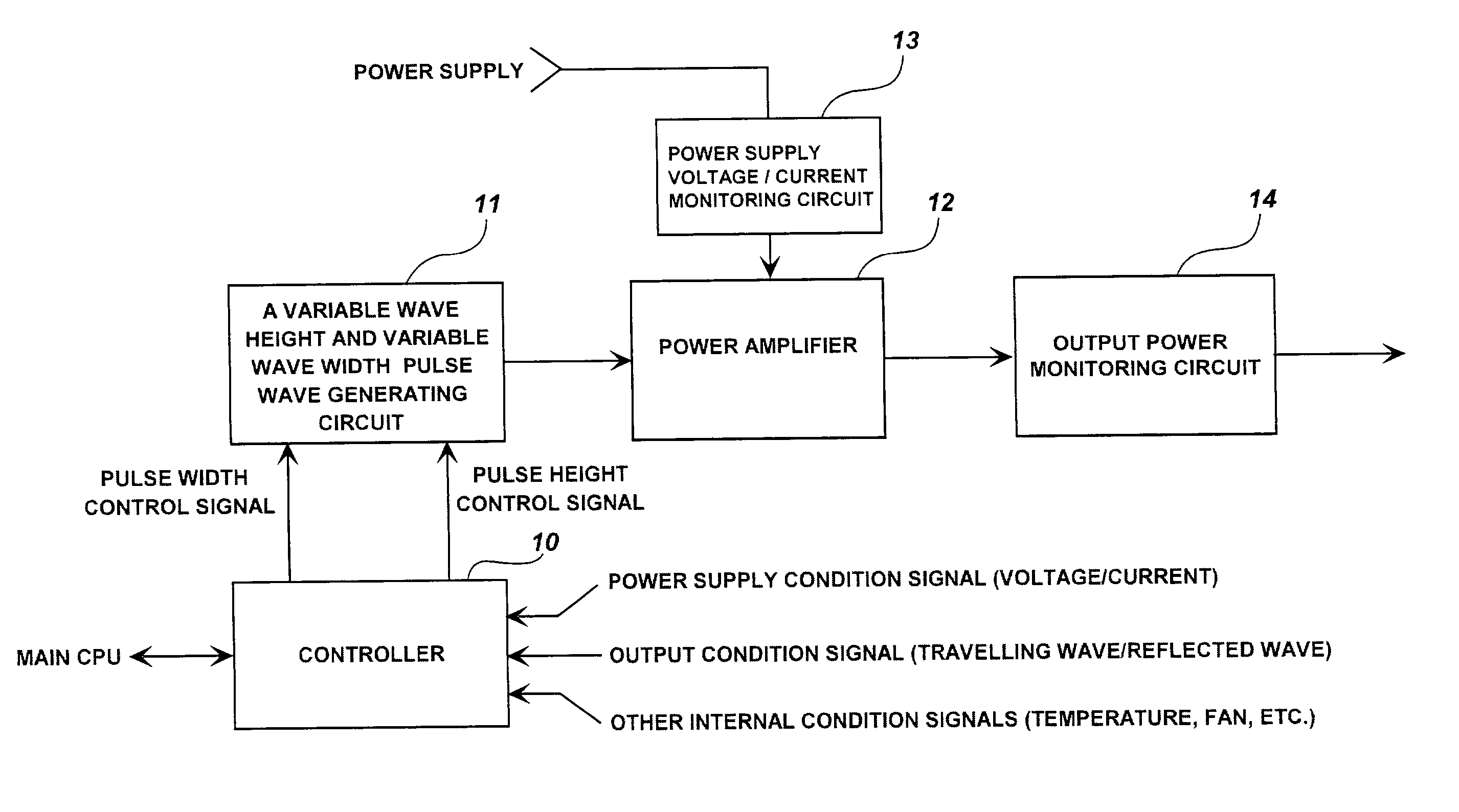
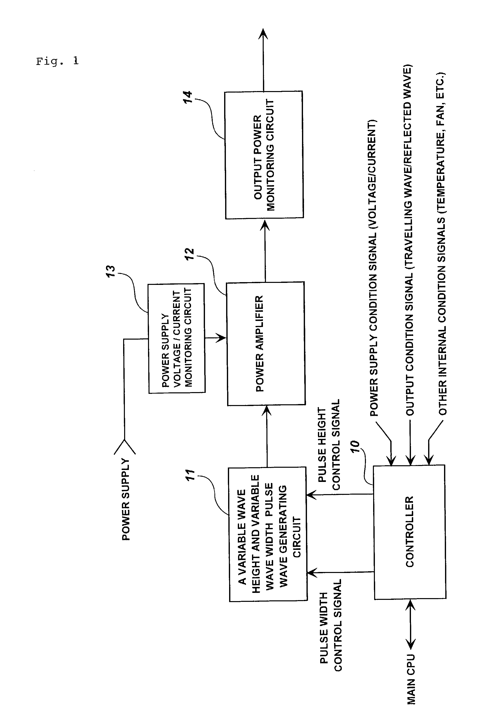
[0030] Hereinafter, embodiments of the present invention will be described in detail with reference to the drawings.

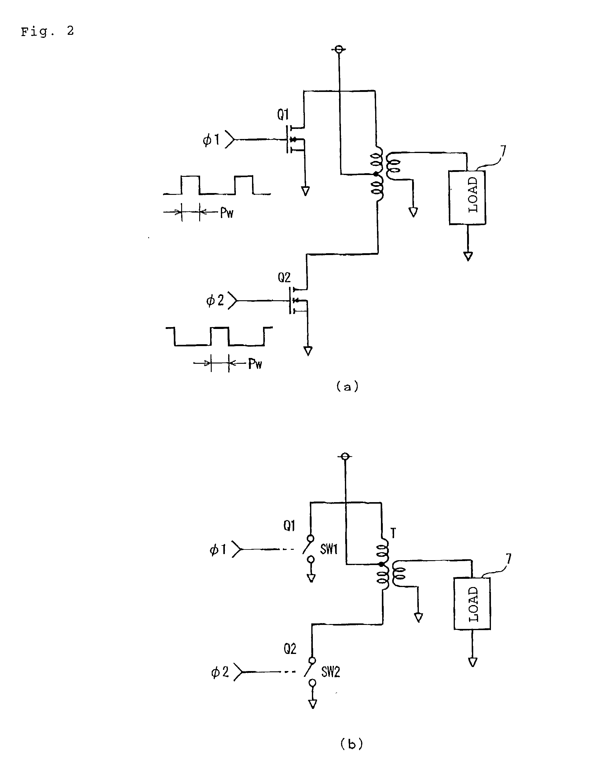
[0031] First, Invention I will be described. A D / E class switching circuit is structured, for example, as shown in FIGS. 2A and 2B. Parts identical with those in FIGS. 5A and 5B are designated by like references. FIG. 2A is the switching circuit and FIG. 2B is an equivalent circuit thereof. This circuit is directed to a transformer coupling push / pull amplifier using an FET as the D / E class switching element, which shows a saturated operation power amplifier. In this example, there is used the FET as the switching element, but the same structure is applied even in the case where another switching element is employed.

[0032] Input pulse waves which are represented by .phi.1 and .phi.2 are inputted to the gates of FETs Q1 and Q2. The input pulse waves .phi.1 and .phi.2 have the same frequency f as that of a target radio frequency and 50% in the maximum duty ratio, and .phi...


PUM

PropertyMeasurementUnit
power lossaaaaaaaaaa
widthaaaaaaaaaa
poweraaaaaaaaaa

Abstract

The present invention relates to a radio frequency amplifier and a method of driving the radio frequency amplifier, and an object of the present invention is to provide a radio frequency amplifier and a method of driving the radio frequency amplifier which are excellent in the controllability at the time of a low power output while keeping the advantage of a high efficiency and give the heating generated by a power loss of such a degree that dewing generated due to over-cooling by the cooling system is not generated at the time of a low power output. The radio frequency amplifier is structured by a variable wave height and variable wave width pulse wave generating circuit 11 that generates a pulse wave (rectangular wave) having an arbitrary pulse height and pulse width, and a power amplifier 12 that is driven by the rectangular wave.

Description

TECHNICAL FIELD OF INVENTION[0001] The present invention relates a radio frequency amplifier and a method of driving the radio frequency amplifier, and more particularly to a radio frequency amplifier that generates a radio frequency plasma, and most particularly to a radio frequency amplifier for generating an inductively coupled plasma used in an inductively coupled plasma mass spectrometer (ICP-MS) and an inductively coupled plasma optical or atomic emission spectrometer (ICP-OES / AES) and a method of driving the radio frequency amplifier. However, the present invention is also widely applicable to general radio frequency amplifiers.[0002] FIG. 1 is a block diagram showing the most general operation in accordance with an embodiment of the present invention.[0003] FIG. 2 is diagrams showing a radio frequency amplifier in accordance with an embodiment of the present invention, which corresponds to claim 5.[0004] FIG. 3 is diagrams showing a radio frequency amplifier in accordance wi...

Claims


Application Information

Patent Timeline
Patent Type & Authority Applications(United States)
IPC IPC(8): G01N21/73H03F1/02G01N27/62H03F3/26
CPCH03F3/265H03F2200/534H03F2200/541
Inventor KANDA, TETSUYA
Owner AGILENT TECH INC
Why Eureka
Try Eureka