Electric power tool

a technology of electric power tools and power tools, which is applied in mechanical energy handling, emergency protective arrangements for automatic disconnection, gas-filled discharge tubes, etc., can solve the problems of inability to make an electrical connection between the illuminator and the motor side contact of the main switching circuit, the base voltage becomes incapable of turning on the illuminator, and the motor terminal short circui

Active Publication Date: 2011-12-13
MAKITA CORP
View PDF9 Cites 20 Cited by
  • Summary
  • Abstract
  • Description
  • Claims
  • Application Information

AI Technical Summary

Benefits of technology

[0009]Recently, switching modules in which a main switching circuit and a forward-reverse switching circuit are incorporated, and electric power tools in which such switching modules are adopted have been developed. Such switching modules enable simplification of the circuit configuration of the electric power tools, and thereby reducing costs for assembling the tools.
[0014]In this electric power tool, the base terminal of the switching element does not have to be electrically connected to a motor side contact of a main switching circuit. Accordingly, a switching module in which the main switching circuit is incorporated can be advantageously adopted, in order to reduce costs for assembling the electric power tool.
[0017]This configuration and the employment of the capacitor enables prolonged voltage application to the base terminal even after the main switching circuit is turned OFF, in order to keep the light of the illuminator to be in ON state for a predetermined period.

Problems solved by technology

However, the switching modules involve difficulty in leading out a signal line from the motor side contact of the main switching circuit, since the main switching circuit is incorporated therein.
Accordingly, if the switching module of this type is adopted in the aforementioned electric power tool, it becomes impossible to make an electrical connection between the illuminator and the motor side contact of the main switching circuit.
However, when the direction of the DC voltage which is applied to the motor terminals is reversed by the forward-reverse switching circuit, the base voltage then becomes incapable of turning ON the illuminator.
Of course, both of the motor terminals can not be simply connected to the base terminal, which causes short circuit of the motor terminals.

Method used


Image

  • Electric power tool
  • Electric power tool
  • Electric power tool

Examples


Embodiment Construction

Preferred Features of an Embodiment of the Invention

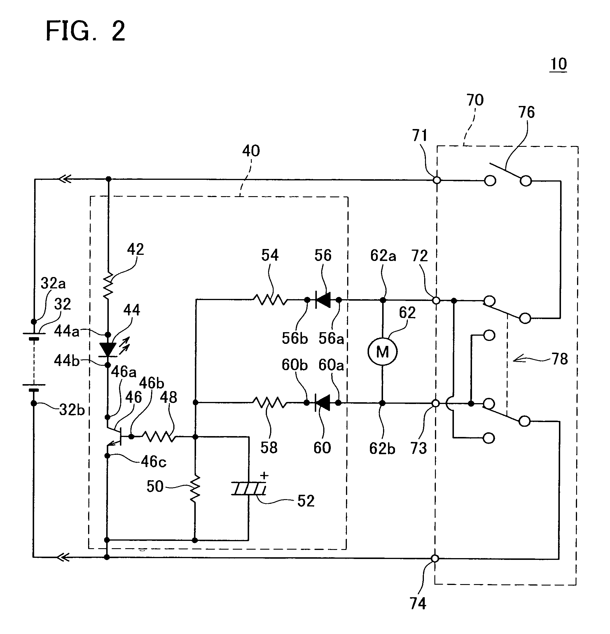
[0022]Some of the preferred features of an embodiment of the invention are described in the followings.[0023](Feature 1) In a switching device, transistors such as NPN transistors or field-effect transistors are preferably used.[0024](Feature 2) In rectifying devices, diodes are preferably used.[0025](Feature 3) A main switching circuit and a forward-reverse switching circuit are preferably integrally configured as a switching module.[0026](Feature 4) A capacitor is connected to a base terminal of a switching device and an emitter terminal.

Embodiment of the Invention

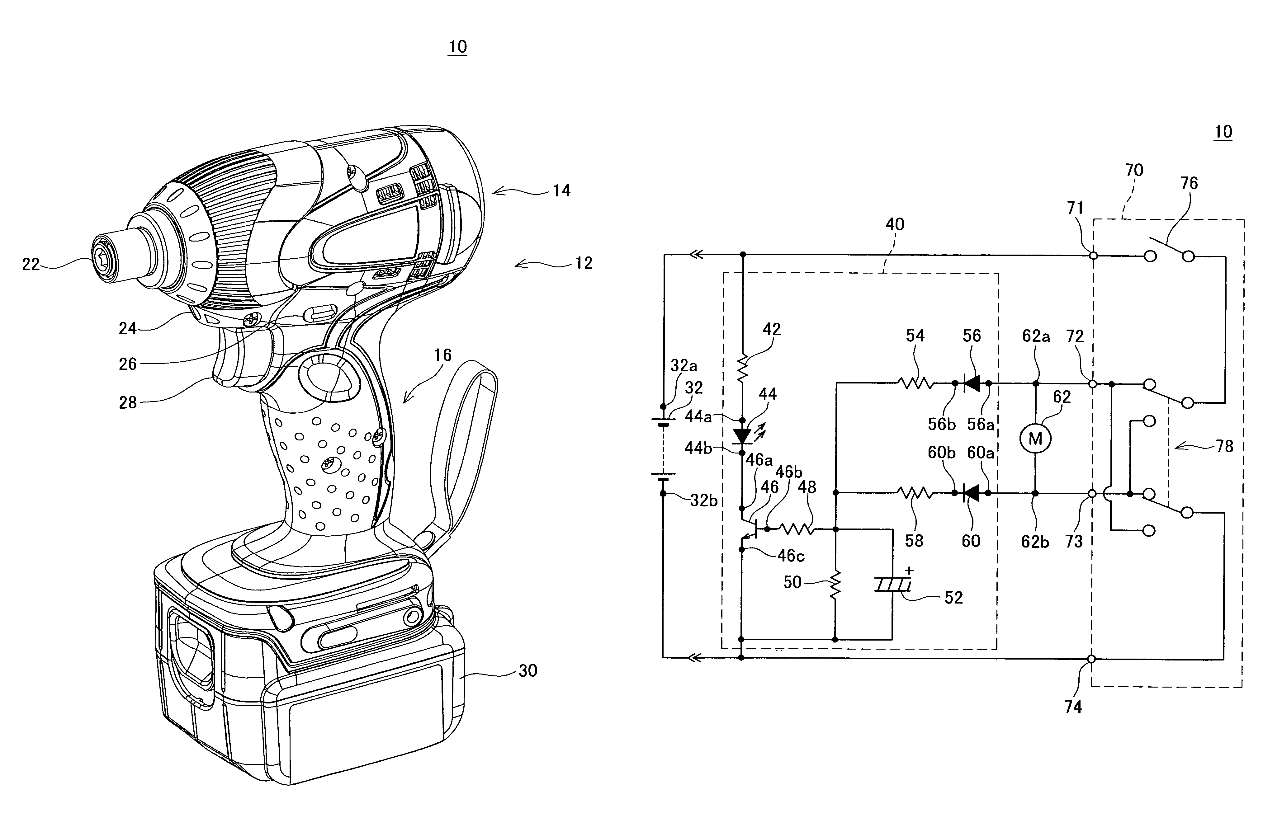
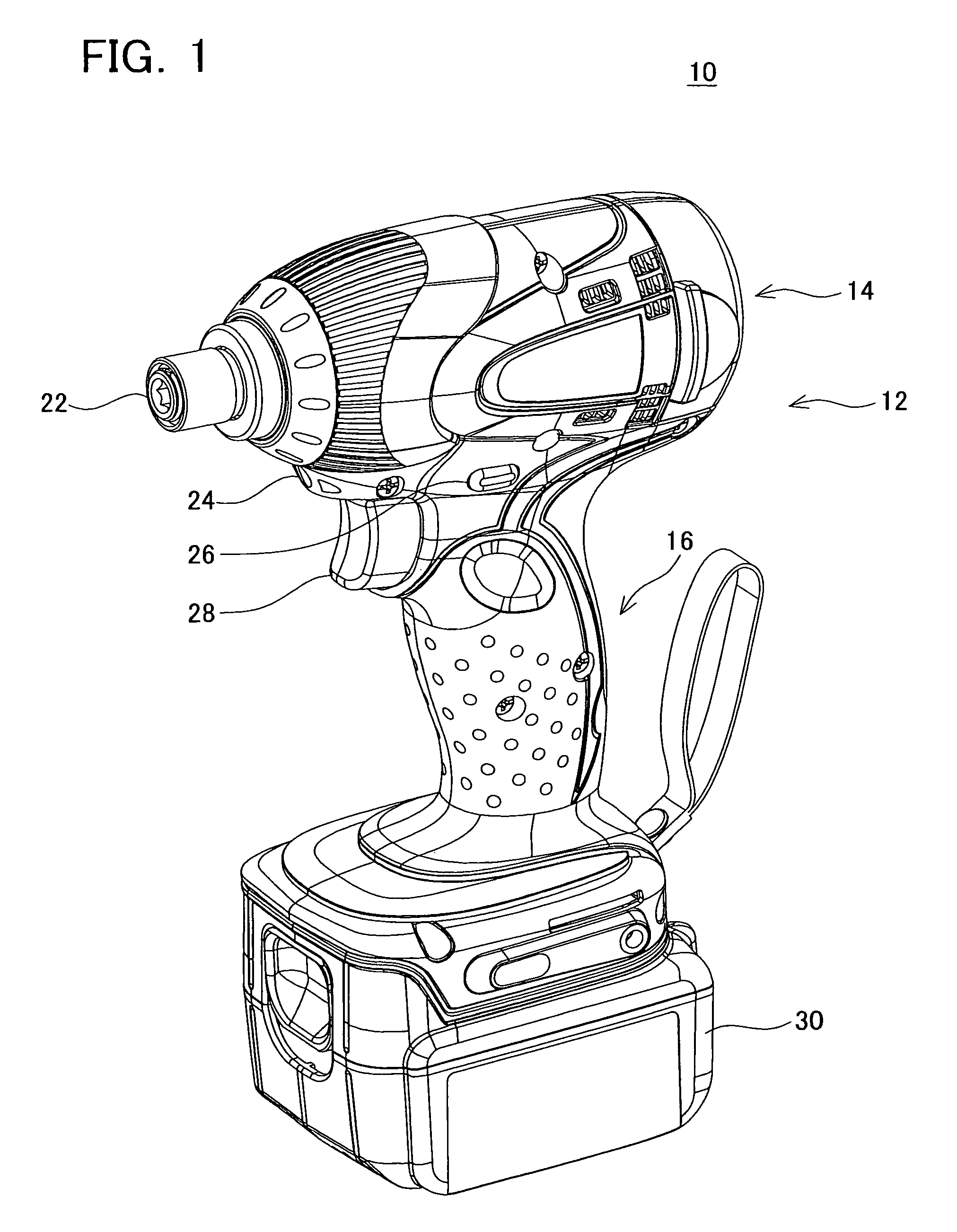
[0027]An electric power screw driver according to the invention is described with reference to the attached drawings. An electric power screw driver is one of electric power tools, which is used for screwing. The embodiment according to the invention adopts an electric power screw driver using impact method (electric power impact screw driver). It should be noted that t...


PUM


Abstract

An electric power tool, which comprises a motor that drives a tool, a power source unit that applies voltage to the motor, a main switching circuit that makes / breaks an electrical connection between the power source unit and the motor, an illuminator that illuminates a work spot, a switching device that electrically connects the illuminator to the power source unit, and an OR circuit that is electrically connected to terminals of the motor to the base terminal is provided. The OR circuit electrically connects one of the motor terminals at which a voltage is higher to the base terminal.

Description

CROSS-REFERENCE TO RELATED APPLICATION[0001]This application claims priority to Japanese Patent Application No. 2007-297498, filed on Nov. 16, 2007, the contents of which are hereby incorporated by reference into the present application.BACKGROUND OF THE INVENTION[0002]1. Field of the Invention[0003]The present invention relates to an electric power tool, and specifically to an electric power tool having an illuminator that illuminates a work spot.[0004]2. Description of the Related Art[0005]U.S. Pat. No. 6,318,874 B1 discloses an electric power tool that comprises a motor for driving a tool, a power source unit (battery) that applies DC voltage to the motor terminals of the motor, a main switching circuit that makes / breaks an electrical connection between the motor terminals and the power source unit, and a forward-reverse switching circuit that switches a direction of the DC voltage which is applied from the power source unit to the motor terminals via the main switching circuit.[...

Claims


Application Information

Patent Timeline
Patent Type & Authority Patents(United States)
IPC IPC(8): B25B23/18
CPCB25F5/00
Inventor WATANABE, MASAHIROSUZUKI, JIROKUSAKAWA, TAKUYA
Owner MAKITA CORP
Why Eureka
Try Eureka