Generator with aluminum winding and wind turbine

a technology of wind turbine and generator, which is applied in the direction of electric generator control, machines/engines, mechanical equipment, etc., can solve the problems of difficult transportation and mantling of generators, and achieve the effects of reducing the weight of the generator, increasing the power efficiency of the generator, and simplifying the installation of the generator in the electrical machine or power plan

Inactive Publication Date: 2011-11-24
SIEMENS AG
View PDF7 Cites 19 Cited by
  • Summary
  • Abstract
  • Description
  • Claims
  • Application Information

AI Technical Summary

Benefits of technology

[0004]The power efficiency of a generator, especially of a large direct drive generator, can be increased by reducing the weight of the generator. Moreover, the installation of a generator in an electrical machine or power plant can be simplified if the weight of the generator is reduced. A reduced weight of the generator would also reduce the installation costs.
[0005]Therefore, it is a first objective of the present invention to provide a generator, where the winding weight is reduced. It is a second objective of the present invention to provide an advantageous wind turbine.

Problems solved by technology

In a direct drive permanent magnet generator windings are typically made of copper which is a relatively heavy metal and thereby results in a heavy generator which may create difficulties for transport and mantling of the generator.

Method used


Image

  • Generator with aluminum winding and wind turbine
  • Generator with aluminum winding and wind turbine
  • Generator with aluminum winding and wind turbine

Examples


Embodiment Construction

[0028]An embodiment of the present invention will now be described with reference to FIGS. 1 to 5.

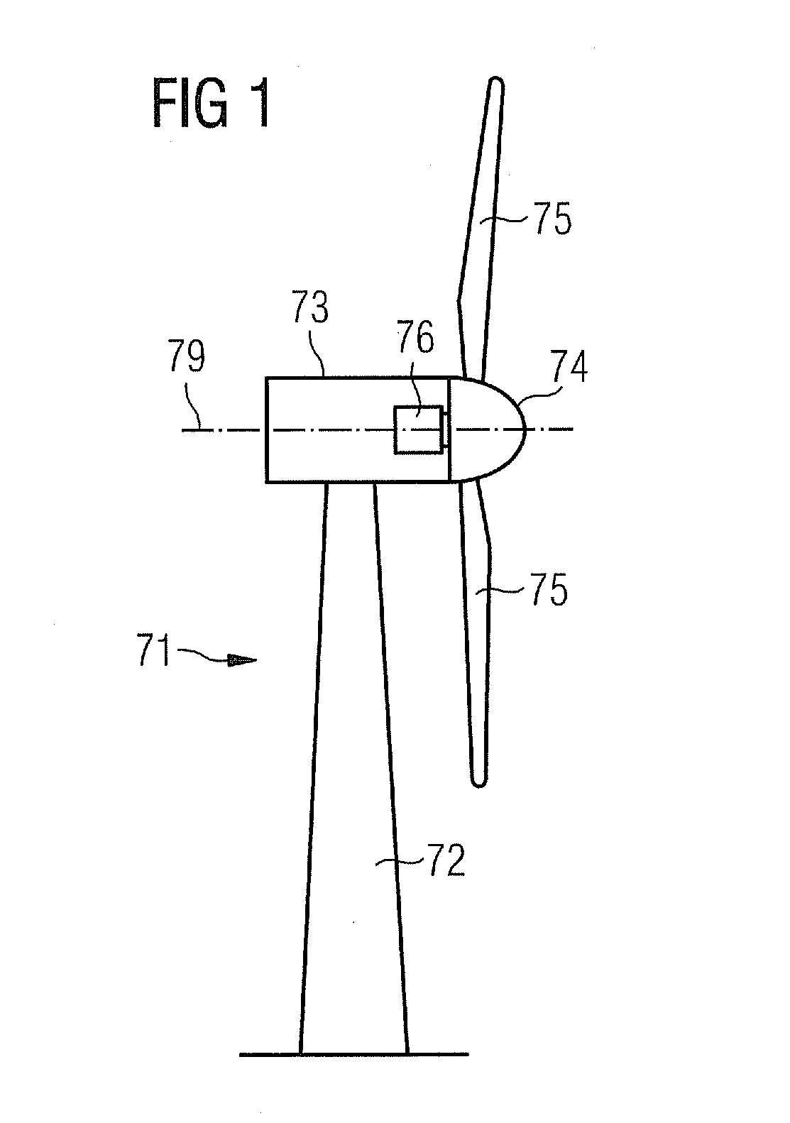
[0029]FIG. 1 schematically shows a wind turbine 71. The wind turbine 71 comprises a tower 72, a nacelle 73 and a hub 74. The nacelle 73 is located on top of the tower 72. The hub 74 comprises a number of wind turbine blades 75. The hub 74 is mounted to the nacelle 73. Moreover, the hub 74 is pivot-mounted such that it is able to rotate about a rotation axis 79. A generator 76 is located inside the nacelle 73. The wind turbine 71 is a direct drive wind turbine.

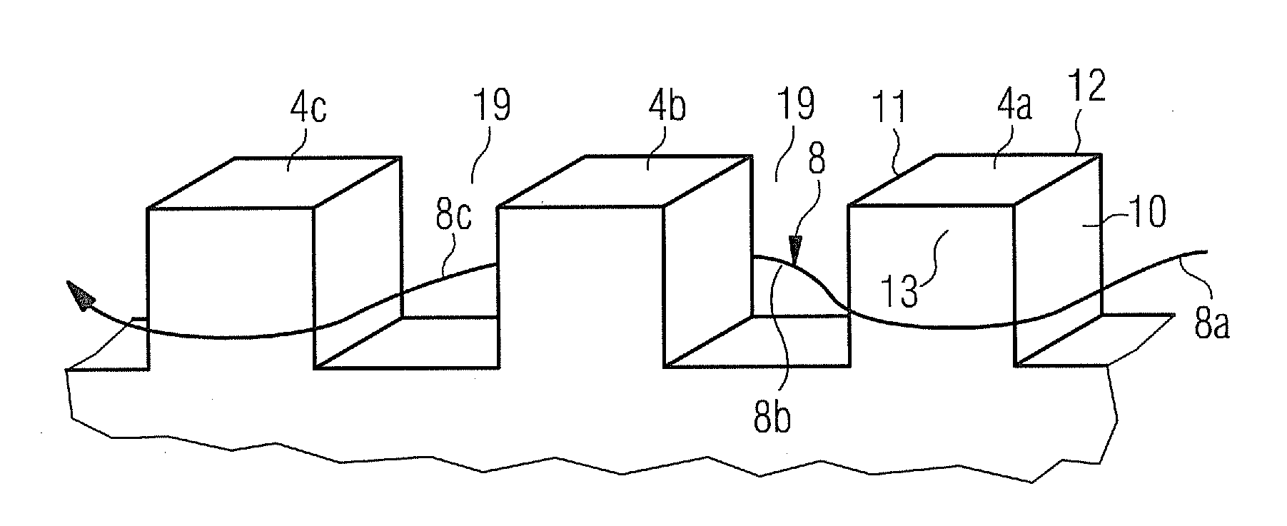
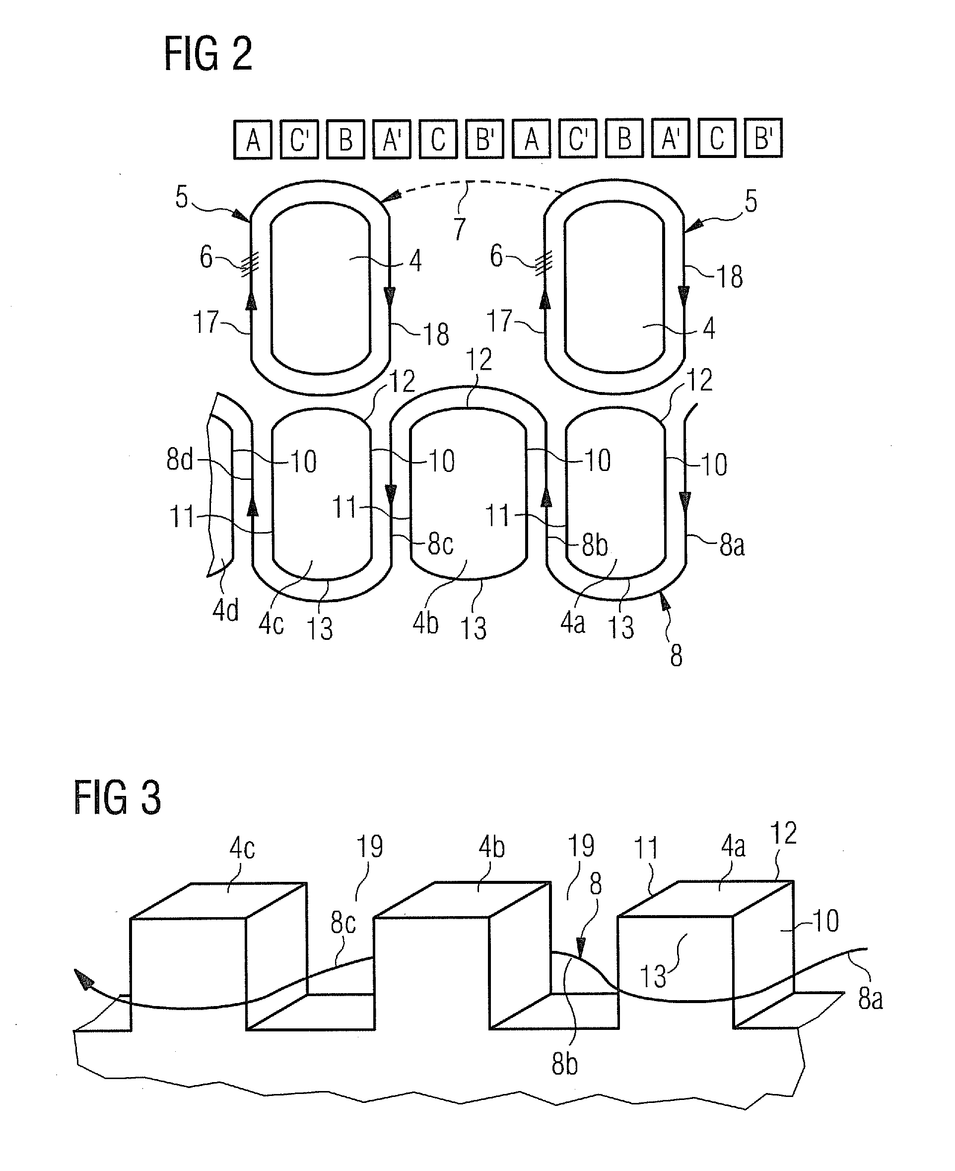
[0030]FIG. 2 schematically shows a comparative illustration of multi-turn and single turn wave windings for one phase and four poles. The upper part of FIG. 2 shows the distributed winding with slots per pole and phase equal to 1 for a 3-phase machine, phases A, B and C. A, B and C correspond to Go direction of the phases and A′, B′ and C′ correspond to Return direction, i.e. opposite direction, of the phases.

[0031]In the middle pa...


PUM


Abstract

A generator is provided that includes at least one conductor. The conductor is made up of aluminium. In a preferred embodiment, the generator includes at least one pole set representing one phase, each pole set having a plurality of poles, and the at least one conductor is turned about the poles of a particular pole set such that only half a single turn is associated to each pole of the particular pole set.

Description

[0001]This application claims priority of European Patent Office application No. 10163301.4 EP, filed May 19, 2010, which is incorporated by reference herein in its entirety.FIELD OF INVENTION[0002]The present invention relates to a generator and to a wind turbine.BACKGROUND OF INVENTION[0003]In a direct drive permanent magnet generator windings are typically made of copper which is a relatively heavy metal and thereby results in a heavy generator which may create difficulties for transport and mantling of the generator.SUMMARY OF INVENTION[0004]The power efficiency of a generator, especially of a large direct drive generator, can be increased by reducing the weight of the generator. Moreover, the installation of a generator in an electrical machine or power plant can be simplified if the weight of the generator is reduced. A reduced weight of the generator would also reduce the installation costs.[0005]Therefore, it is a first objective of the present invention to provide a generat...

Claims


Application Information

Patent Timeline
Patent Type & Authority Applications(United States)
IPC IPC(8): F03D9/00H02K3/28
CPCH02K3/02H02K3/14H02K7/1838Y02E10/725H02K3/28Y02E10/72
Inventor GROENDAHL, ERIKKIMIABEIGI, MOHAMMADSTIESDAL, HENRIK
Owner SIEMENS AG
Why Eureka
Try Eureka