Optical Sensors

a technology of optical sensors and gratings, applied in the field of optical sensors, can solve the problems of difficult control in the geometry of the fibre, tedious work of the fibre, etc., and achieve the effect of simplifying the structure and fabrication of the sensor

Inactive Publication Date: 2008-02-21
UNIV OF SOUTHAMPTON
View PDF6 Cites 18 Cited by
  • Summary
  • Abstract
  • Description
  • Claims
  • Application Information

AI Technical Summary

Benefits of technology

[0014] In some embodiments, the optical sensor may further comprise: a substrate on which the sensing element and the analysing element are positioned; an input waveguide defined on the substrate and arranged to deliver light from a light source to the sensing element; a connecting waveguide defined on the substrate and arranged to deliver light output by the sensing element to the analysing element; and an output waveguide defined on the substrate and arranged to deliver light output by the analysing element for detection by an optical power detector. Placing the two elements on the same substrate is particularly advantageous since they will have more similar environments so that the output of the sensor is less subject to errors caused by disturbances to only one of the elements. Also, the fabrication and structure of the sensor is simplified; direct ultraviolet writing techniques can be used to define the components of the whole sensor in a single processing step.
[0015] The connecting waveguide may be arranged to deliver a portion of

Problems solved by technology

However, the use of fibre gratings requires tedious working of the fibre to expose the waveguiding core to the liquid, such as by et

Method used


Image

  • Optical Sensors
  • Optical Sensors
  • Optical Sensors

Examples


Embodiment Construction

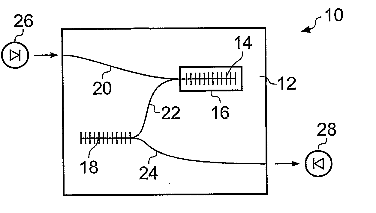
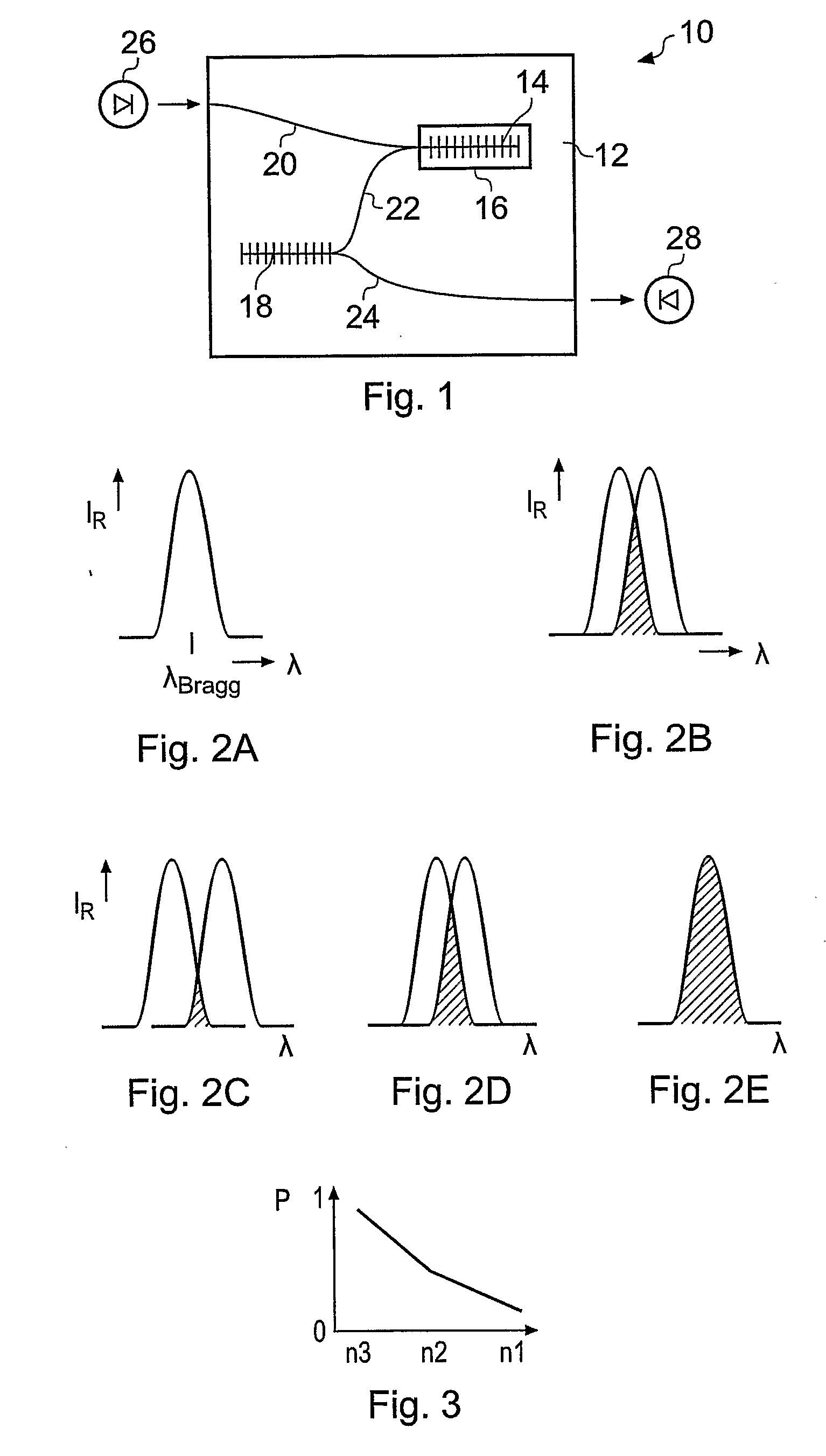
[0041] An optical reflective grating such as a Bragg grating comprises a periodic modification of refractive index within an optical waveguiding structure, where the waveguiding structure comprises a core surrounded by a cladding material of a lower refractive index than the core. This structure guides optical waves by total internal reflection at the boundary between the two refractive indices. The grating reflects light propagating along the waveguide of wavelengths that falls within a bandwidth defined by the magnitude and dimensions of the periodic refractive index modification, and transmits light of other wavelengths.

[0042] If a region of the core of the waveguide is exposed or nearly exposed by removing all or part of a portion of the cladding, and a fluid applied to the region so that the optical field of light propagating in the waveguide extends into the fluid, the refractive index of the fluid modifies the effective modal index experienced by the propagating light. This ...


PUM


Abstract

An optical sensor comprises a sensing element comprising a waveguide grating with a response that varies with an effective modal index experienced by light propagating in the grating and a sample window for receiving fluid which affects the effective modal index to modify the response, the sensing element arranged to receive light from a light source and to output the light after filtering; and an analysing element comprising a second waveguide grating having a second response, and arranged to receive light output by the sensing element and to output the light after filtering for detection by an optical power detector. The combination of the two gratings converts changes in the wavelength of light output by the sensing element in response to the sample of fluid to changes in the amount of light, allowing the fluid index to be deduced from a measurement of optical power. The two elements may be fabricated on a single substrate to reduce errors from environmental disturbances such as temperature changes.

Description

BACKGROUND OF THE INVENTION [0001] The present invention relates to optical sensors, particularly but not exclusively to optical sensors based on planar waveguide gratings for sensing the refractive index of fluid samples and parameters and characteristics related thereto. [0002] Measurement of the optical refractive index of fluids is of importance in fields including bioanalysis and biosensing. Different fluids, or concentrations of the same fluid, have different refractive indices so that the fluids can be identified or distinguished from refractive index measurements. The refractive index or change in refractive index of a fluid can be used to determine many biologically important measurands such as protein concentrations and glucose levels. In other fields, refractive index measurements are used in applications as diverse as process control and the detection of explosives [1]. [0003] Various devices and techniques for measuring refractive index are known. These include the Abbe...

Claims


Application Information

Patent Timeline
IPC IPC(8): G01B9/02G01N21/41
CPCG01N21/4133G01N21/553
Inventor EMMERSON, GREGORY DANIELGAWITH, CORIN BARRY EDMUNDSMITH, PETER GEORGE ROBIN
Owner UNIV OF SOUTHAMPTON
Why Eureka
Try Eureka