

Method and apparatus for a network queuing engine and congestion management gateway
a network queuing engine and gateway technology, applied in the field of network queuing engines and congestion management gateways, can solve the problems of affecting the performance of applications relying on, affecting the delivery of data traffic, and affecting the performance of applications
- Summary
- Abstract
- Description
- Claims
- Application Information
AI Technical Summary
Problems solved by technology
Method used
Image

Examples
example architecture
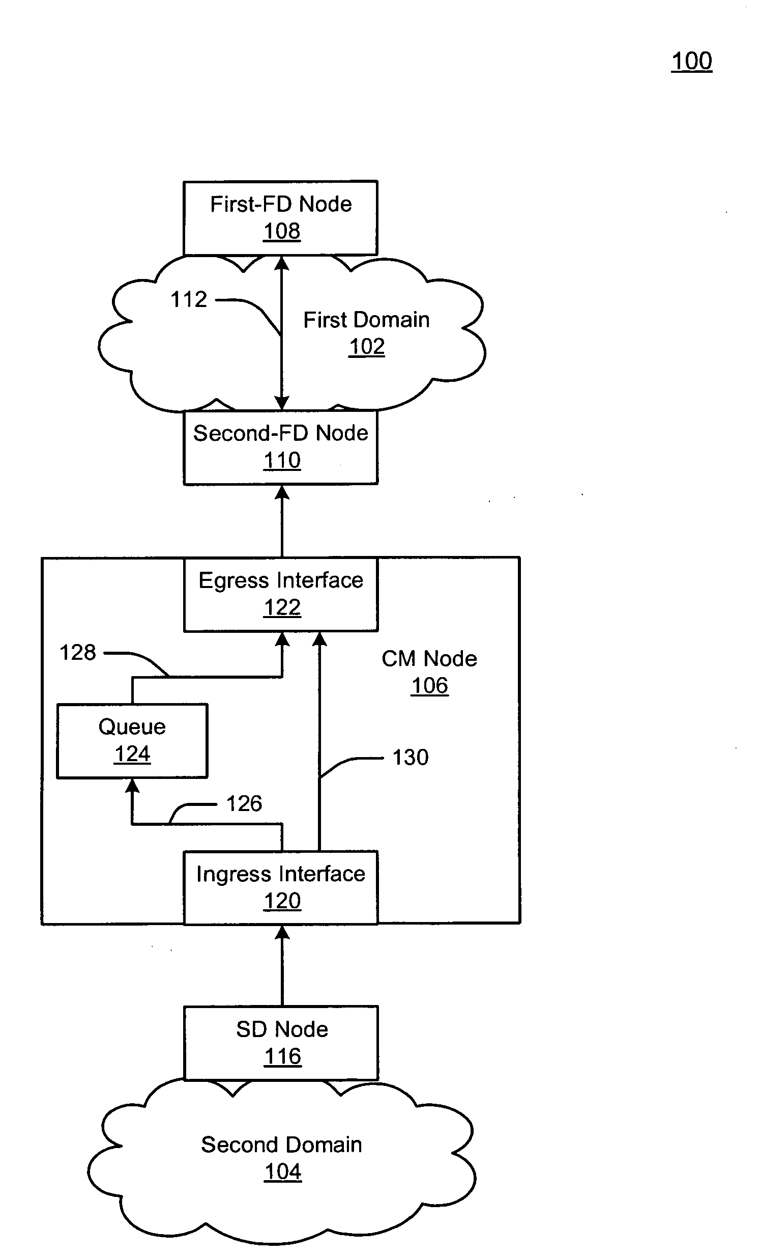
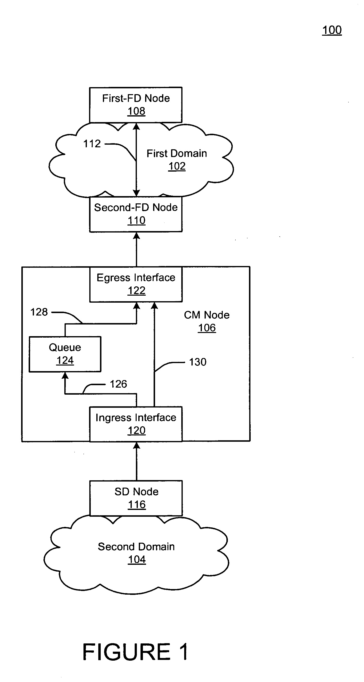
[0039]FIG. 3 is a block diagram illustrating an example network 300 in accordance with one or more aspects of the technology. The network 300 may include a FD 302, a SD 304 and a gateway 306 that straddles both the FD and SD 302,304. As described in more detail below, the FD 302 employs a common protocol for performing congestion management within the first domain 102 (hereinafter “CM protocol”), and the SD 304 does not.
[0040]The FD 302 may be a partial or full deployment of most any communication or computer network, including any of a public or private, terrestrial wireless or satellite, or wireline network. The FD 302 may include a first and second access nodes (“FD-access node”) 308, 310. The FD 302 may also include first and second end nodes (“FD-end nodes”) 312, 314; each of which may be, for example, a server or other computer.
[0041]Each of the first and second FD-access nodes 308, 310 may be an interconnect device, such as a network switch, bridge and the like. Accordingly, ...
example congestion
Control
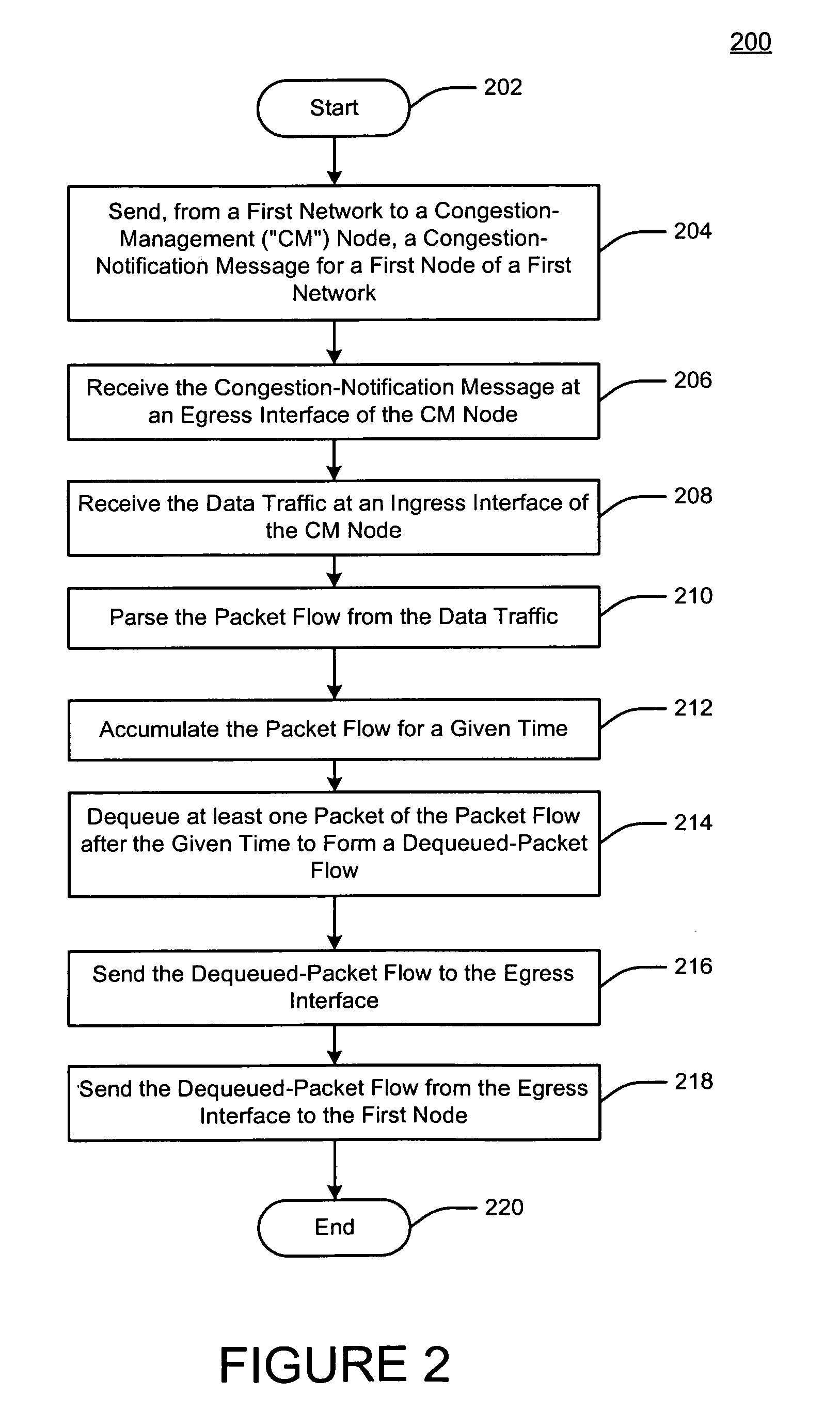
[0067]FIG. 4 is a flow diagram illustrating an example flow 400 for performing congestion management. For convenience, the following describes the flow 400 with reference to operation of the gateway 306 of FIG. 3. The flow 400 may be carried out using other architectures as well.
[0068]Prior to an initiation of the flow 400 at process block 402, the gateway 306 becomes operative, such the operating system 338, queuing engine 340 and CM-protocol stack 342 are retrieved from the memory 330 and executed by the processor 328. As such, the gateway 306 functions as a specially programmed computer for carrying out any of the functions noted above and below. Any reference below to the queuing engine 340 and CM-protocol stack 342 assumes that they and the directives therein are under execution by the processor 328.
[0069]Also, at a time just prior to the initiation of the flow 400, the first FD-access node 308 has not ascertained that congestion is detrimentally affecting either of the ...
example alternative
Architecture
[0098]FIG. 5 is a block diagram illustrating an example network 500 in accordance with one or more aspects of the technology. The network 500 may be, for example, a segment of a larger computer cluster network or domain 502. The network 500 may include an access node 504, first and second end nodes 506, 508 and a CM node 510.
[0099]The first and second end nodes 506, 508 may be, for example, servers or other computers. The first and second end nodes 506, 508 may communicate using any of a standardized, proprietary, open-source, and freely-available communication protocol for communicating in packet data networks and the like. For example, the first and second end node nodes 506, 508 may communicate using one or more of the IEEE 802.3 standards, including any of the Fast Ethernet, GE and 10GE protocols. Accordingly, the first and second end nodes 506, 508 may include or have assigned thereto first and second addressed, respectively. These first and second “end node” addres...
PUM
 Abstract
Description
Claims
Application Information