Separator for fuel cell

a fuel cell and separator technology, applied in the direction of fuel cells, electrical equipment, electrochemical generators, etc., can solve the problems that the miniaturization of the separator cannot be said to be sufficiently achieved, and the shape provided by the marker such as the corner cut has not been investigated from a viewpoint of coordination with the structure of the separator, so as to achieve the effect of smoothing the flow of fluid in the fuel cell

Inactive Publication Date: 2009-10-29
TOYOTA JIDOSHA KK
View PDF3 Cites 0 Cited by
  • Summary
  • Abstract
  • Description
  • Claims
  • Application Information

AI Technical Summary

Benefits of technology

[0007]However, a membrane-electrode assembly having a shape provided with a marker such as a corner cut as described above has not sufficiently been investigated from a viewpoint of coordination with the structure of a separator. Accordingly, it cannot be said that the miniaturization of the separator is sufficiently achieved. Moreover, when further coordination of the membrane-electrode assembly with the separator is achieved, the flow of a fluid in a fuel cell can further be smoothened.
[0008]Therefore, an object of the present invention is to provide a separator capable of achieving miniaturization in a case where a membrane-electrode assembly (MEA) is provided with a cutout and capable of further smoothening the flow of a fluid, and to provide a fuel cell.
[0010]In this separator, a part of the contour of the manifold has a shape along the cutout of the membrane-electrode assembly, and the gas or the coolant to be supplied from the manifold to the cells and to be discharged from the cells to the manifold can be supplied and discharged through the portion along the cutout. In consequence, the reactant gas or the coolant can further smoothly be supplied and discharged. Furthermore, according to such a separator, the coordination with the membrane-electrode assembly having a shape provided with a marker improves, and eventually a compact structure can be realized as a whole to achieve further miniaturization.
[0011]The cutout is, for example, a corner cut provided in the corner of the membrane-electrode assembly and forming the membrane-electrode assembly into an asymmetric shape. Moreover, in this case, a portion of the contour of the manifold facing the corner cut is preferably formed substantially in parallel with the edge of the corner cut. In this case, any portion between the corner cut of the membrane-electrode assembly and the portion of the manifold facing the corner cut has an equal width. That is, the length of a supply or discharge passage connecting the manifold to a power generation or the like becomes the shortest through any portion, so that a pressure loss (a differential pressure) can be decreased, and a loss in an auxiliary device or the like can further be decreased.

Problems solved by technology

However, a membrane-electrode assembly having a shape provided with a marker such as a corner cut as described above has not sufficiently been investigated from a viewpoint of coordination with the structure of a separator.
Accordingly, it cannot be said that the miniaturization of the separator is sufficiently achieved.

Method used


Image

  • Separator for fuel cell
  • Separator for fuel cell
  • Separator for fuel cell

Examples


Embodiment Construction

[0018]A preferable embodiment of the present invention will hereinafter be described with reference to the drawings.

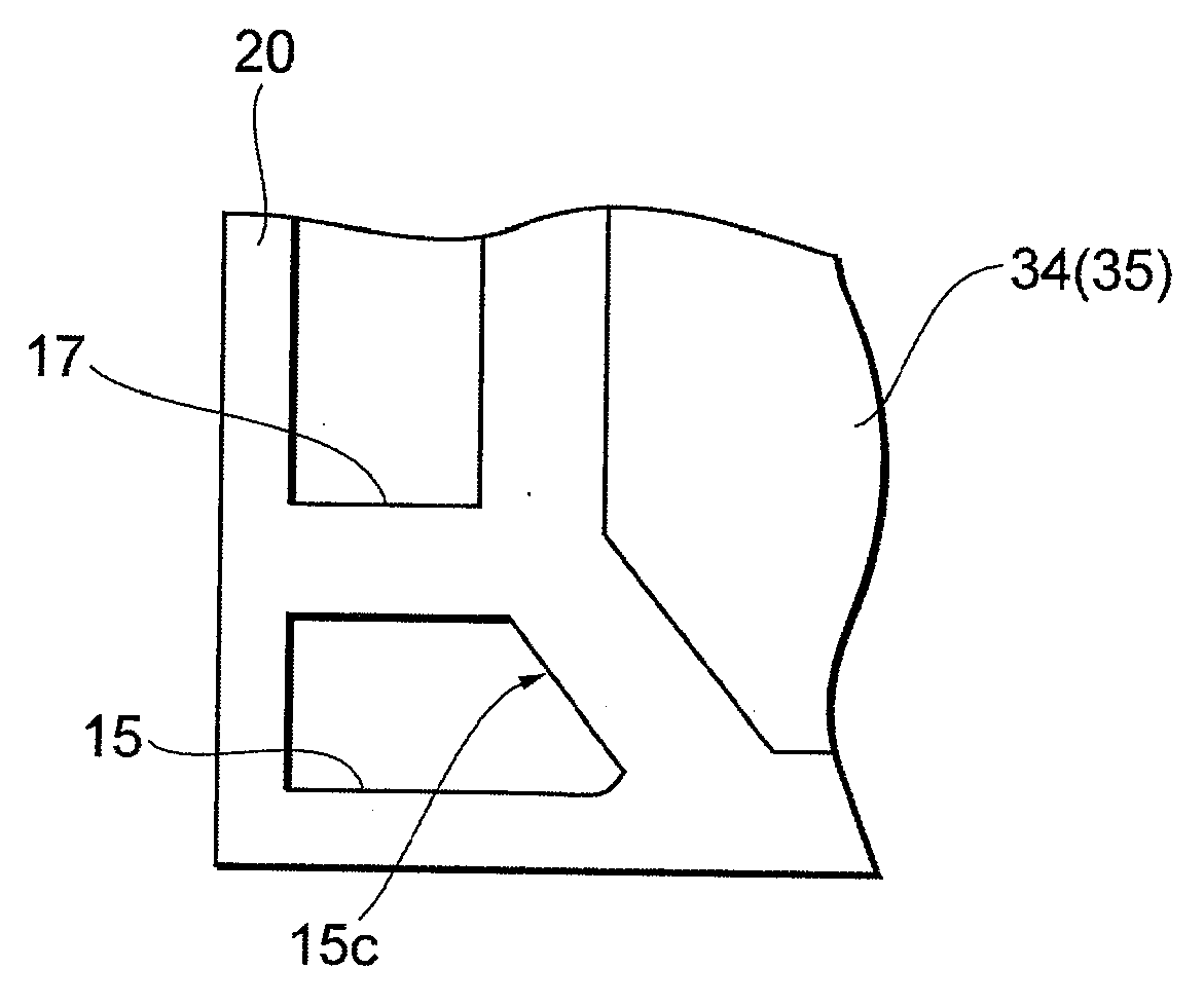
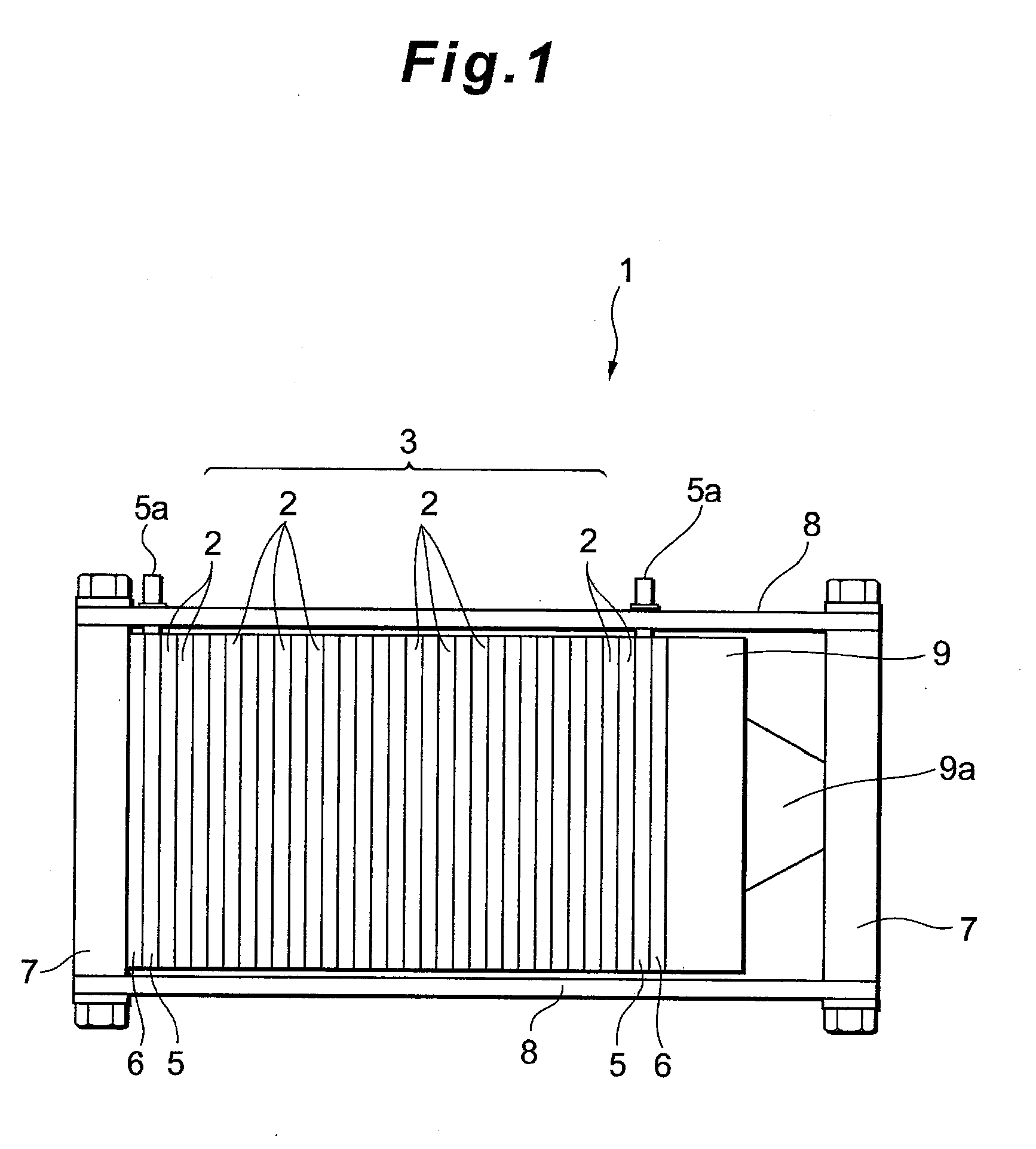
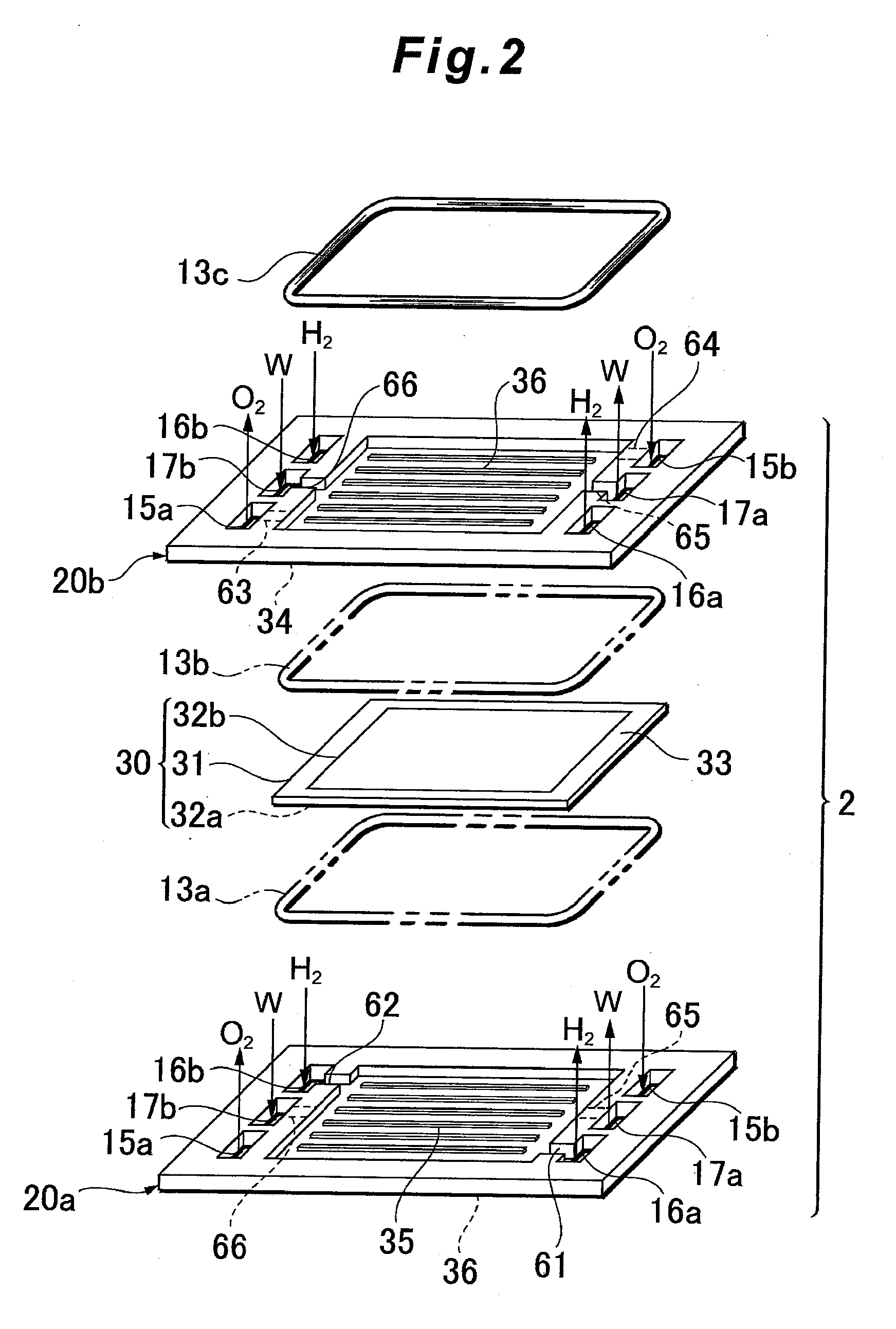
[0019]FIGS. 1 to 4 show embodiments of a fuel cell and a separator for the fuel cell according to the present invention. A separator 20 of a fuel cell 1 is laminated together with a membrane-electrode assembly 30 to constitute a cell 2, and includes manifolds 15, 16 and 17 for supplying to or discharging from the cells 2 a reactant gas and a coolant. In the present embodiment, as to this separator 20, portions of the contours of the manifolds 15, 16 and 17 corresponding to a cutout 30a of the membrane-electrode assembly 30 are formed into a shape along the cutout 30a, and the reactant gas or the coolant is supplied or discharged through the portions having the shape along the cutout 30a (see FIG. 3, etc.).

[0020]In the embodiment described hereinafter, first the schematic constitution of the fuel cell 1 and the schematic constitution of the cell 2 constituting the fuel ...


PUM

PropertyMeasurementUnit
shapeaaaaaaaaaa
structureaaaaaaaaaa
widthaaaaaaaaaa

Abstract

Miniaturization is achieved when a membrane-electrode assembly (MEA) is provided with a cutout, and the flow of a fluid is further smoothened. To realize this, in a separator for a fuel cell according to the present invention, a portion of the contour of a manifold formed in the separator corresponding to a cutout of the membrane-electrode assembly is formed into a shape along the cutout, and a reactant gas or a coolant is supplied or discharged through a portion formed into the shape along the cutout. The cutout is, for example, a corner cut provided in the corner of the membrane-electrode assembly and forming the membrane-electrode assembly into an asymmetric shape. A portion of the contour of the manifold facing this corner cut is preferably formed substantially in parallel with the edge of the corner cut.

Description

BACKGROUND OF THE INVENTION[0001]1. Field of the Invention[0002]The present invention relates to a separator for a fuel cell. More particularly, the present invention relates to the improvement of the structure and shape of a separator provided with a manifold for supplying to or discharging from each cell a reactant gas or a coolant.[0003]2. Description of Related Art[0004]In general, a fuel cell (e.g., a polymer electrolyte fuel cell) has a structure in which a membrane-electrode assembly (MEA) is held between a pair of separators to constitute a cell (a cell constituting the fuel cell) and in which a plurality of cells are laminated. Moreover, the separator is provided with a manifold for supplying to or discharging from each cell a reactant gas (a fuel gas, an oxidizing gas) or a coolant.[0005]In a case where the above-mentioned fuel cell is manufactured, when the membrane-electrode assembly is arranged on the separator to form a module, for example, it needs to be prevented tha...

Claims


Application Information

Patent Timeline
Patent Type & Authority Applications(United States)
IPC IPC(8): H01M8/04
CPCH01M8/0247Y02E60/521H01M8/242H01M8/1004H01M8/0258H01M8/0267H01M8/2483Y02E60/50H01M8/0263
Inventor YAMAMOTO, YOSHINORIYAGAMI, YUICHIAIZAKI, JIROSHIRAHAMA, JUNICHI
Owner TOYOTA JIDOSHA KK
Why Eureka
Try Eureka