
Bioabsorbable band system,a bioabsorbable band, a method for producing a bioabsorbable band, a needle system of a bioabsorbable band and a locking mechanism

a bioabsorbable band and band system technology, applied in the field of bioabsorbable band system, can solve the problems of non-union or breakage of the bone, affecting the healing effect, and the current design of cable and crimp system, especially for surgical use, and achieving significant drawbacks

Active Publication Date: 2009-10-29
BIORETEC
View PDF11 Cites 24 Cited by
  • Summary
  • Abstract
  • Description
  • Claims
  • Application Information

AI Technical Summary

Benefits of technology

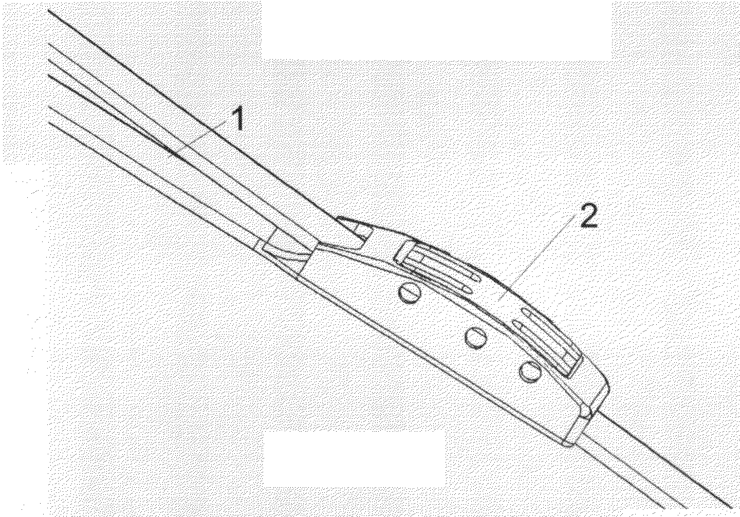
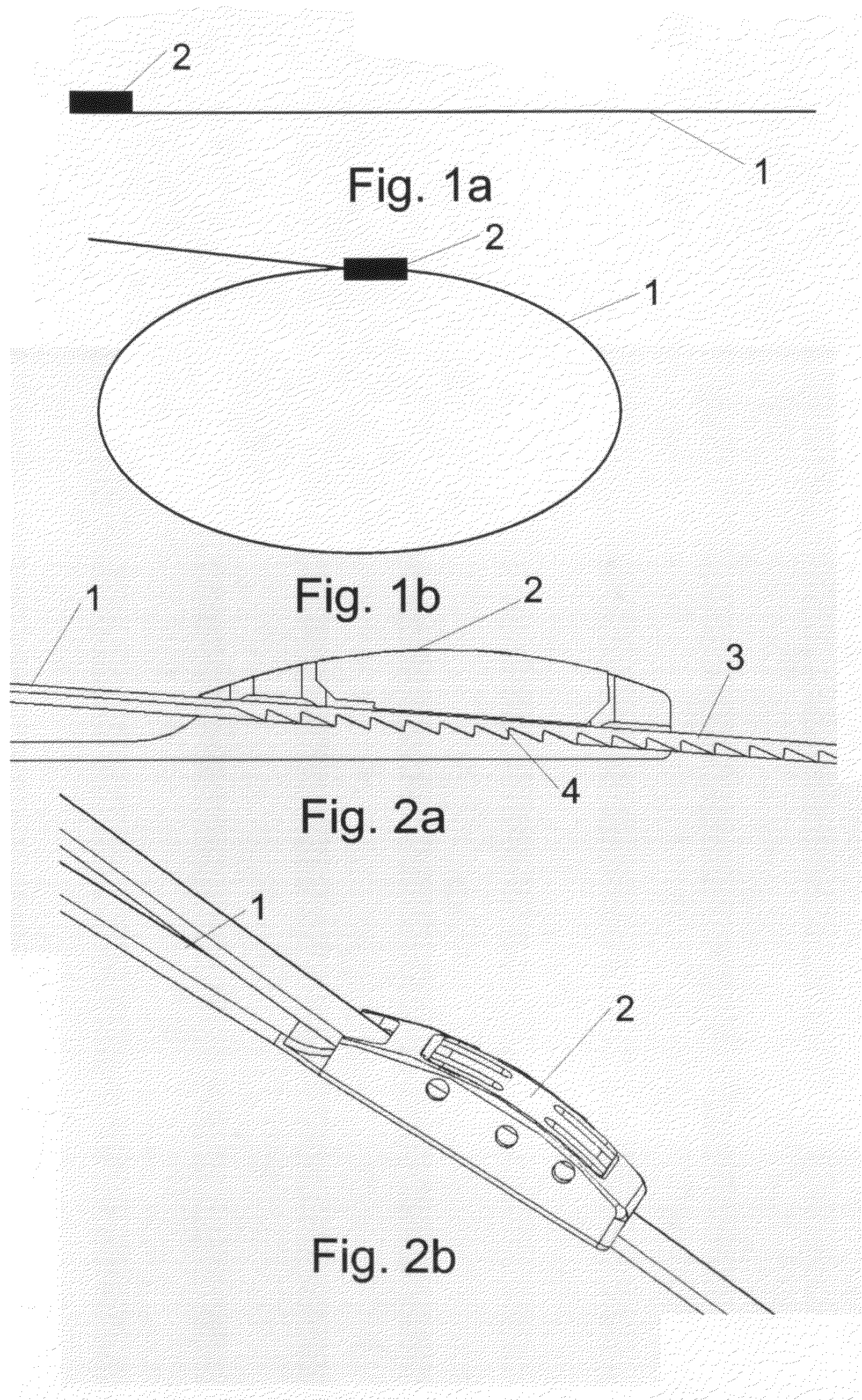
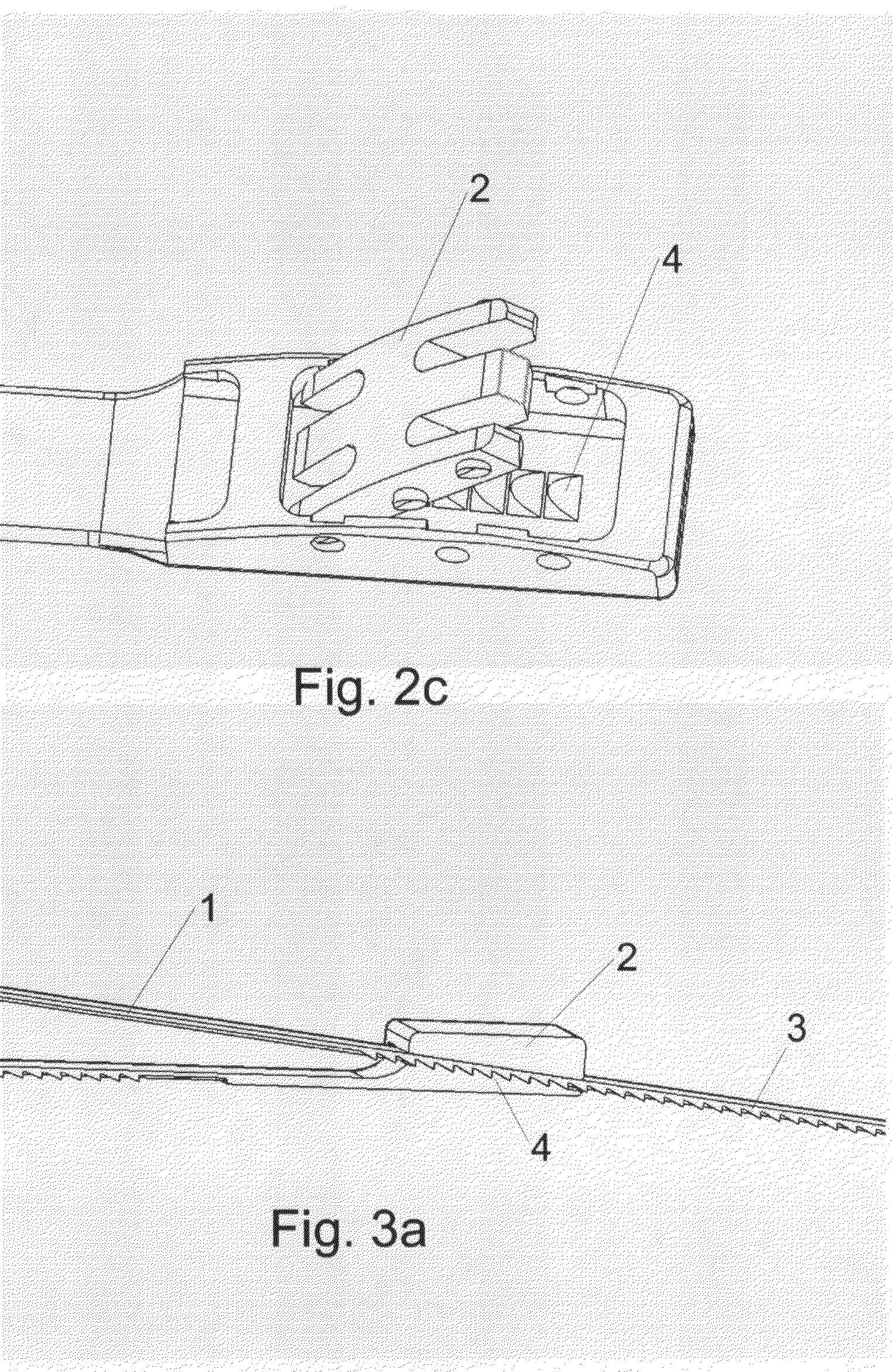
[0008]The present invention diminishes the above-mentioned drawbacks of the prior band systems for securing a bone and provides a bioabsorbable band system comprising a needle system and a bioabsorbable band including a bioabsorbable locking member. The bioabsorbable band system provides accurate tensioning of the band and safe locking of the band around a bone. The bioabsorbable band is used for securing a bone fracture, or an osteotomy, or a soft tissue on a bone. The present invention is mainly utilized in the chest surgery. Besides the chest surgery, the present invention is also usable in orthopaedics and traumatology, like in the femoral bone surgery, with tubular bones and in repair of the patella.General Description
[0017]According to one solution, the band section of the bioabsorbable band is oriented completely but the locking section is not oriented. At the junction of the band section and the locking section then exists a length having an orientation gradient. In such a manner desirable properties can be achieved to the band section, and manufacturing of the locking section becomes easier. After the orientation the band section has a high strength, a good flexibility and an adequate ductility.
[0022]According to an advantageous embodiment of the invention, elements of the system, such as a band and / or a locking member, may have a special coating layer on its surface and may contain one or more bioactive substances, such as antibiotics, chemotherapeutic substances, growth factors like bone morphogenic proteins, substances accelerating the healing of the wound and osteotomy, hormones or other drugs and the like. Such bioactive elements are especially advantageous in surgical use, because they contribute biochemically to the healing of the lesion in addition to providing mechanical support.

Problems solved by technology

Especially troublesome is the constant movement associated with the breathing cycle, to which the bone is subjected, which keeps the sternum in a cyclic strain regime often accompanied by unpredicted mechanical stresses.
Such strains may eventually cause non-union or breakage of the bone.
However, current designs of cable and crimp systems, particularly for surgical use, have significant drawbacks.
For example, a tension, which is too low or too high may lead to improper healing or to poor medical results.
Also, in many prior art cable and crimp systems there is the possibility for slippage of the cable in the crimp, which can lead to delayed healing.
The loosening of the cable, e.g. in bone fracture fixation, can also lead to delayed healing, pain or even to a failure of healing.
Also, many prior art crimps cannot be easily locked at a desired tension, and often the desired tension can not be maintained when using a cable loop or winding as there is an inevitable drop in tension when the pliers are removed.
Thus, a surgeon typically has to “over shoot” the desired tension, guessing how much of that tension will be lost after the crimping has been completed and the pliers removed, thus significantly increasing the possibility for tensioning errors.
In addition, many prior art crimps are bulky and may cause adverse tensioning in the surrounding tissues, which may result in a negative effect on tissue healing.
Another drawback of many prior art cable and crimp systems is that they are made of metal, such as stainless steel.
Such extremely stiff materials are mechanically incompatible with bone tissue and therefore, may cause osteolysis below the material, which may lead to implant migration.

Method used


Image

  • Bioabsorbable band system,a bioabsorbable band, a method for producing a bioabsorbable band, a needle system of a bioabsorbable band and a locking mechanism
  • Bioabsorbable band system,a bioabsorbable band, a method for producing a bioabsorbable band, a needle system of a bioabsorbable band and a locking mechanism
  • Bioabsorbable band system,a bioabsorbable band, a method for producing a bioabsorbable band, a needle system of a bioabsorbable band and a locking mechanism

Examples


example

[0054]70L / 30D,L polylactide (inherent viscosity 6.2 dl / g) is injection moulded to form a band preform. The locking section of the band is heated to 30° C. (which is below the glass transition temperature Tg=55° C.), and the band section of the band is heated to 75° C. The band section is drawn by a draw ratio of 1:5. A compression moulding process is used for finishing the band, for example for forming the pawl teeth. The stainless steel needle is attached to the end of the band section by compression moulding at 75° C. a flexible stainless steel mesh in to the band and passing the mesh through the eye hole at the end of the needle.


PUM

PropertyMeasurementUnit
bioabsorbableaaaaaaaaaa
lengthaaaaaaaaaa
temperatureaaaaaaaaaa

Abstract

A bioabsorbable band system for securing a bone fracture, or an osteotomy, or a soft tissue on a bone. The bioabsorbable band system includes a needle system and a bioabsorbable band including a bioabsorbable locking member. The bioabsorbable band includes a length having an at least partially oriented structure. The bioabsorbable band further includes a locking mechanism with a locking member. Also a method for producing the bioabsorbable band.

Description

FIELD OF INVENTION[0001]The present invention relates to a bioabsorbable band system for securing a bone. The band system comprises a bioabsorbable band including a bioabsorbable locking member and a needle system.BACKGROUND OF THE INVENTION[0002]In bone surgery it is well known to apply longitudinal implants like bands, braids, or wires to fixation of bone fragments to each others. Such implants are made usually of metals or of polymeric materials.[0003]Chest surgery such as, for example, open heart surgery requires opening of the chest and rib cage in order to facilitate access to the organ to be operated. The front central part of the rib cage constitutes a longitudinal bone, the sternum, which overlies the heart and secures the ribs. A specific action performed in such surgery is longitudinal sectioning of the sternum into two halves (“median sternotomy”). After performing the heart surgery, the chest is closed as a part of a reconstitution operation, in which among other activi...

Claims


Application Information

Patent Timeline
Patent Type & Authority Applications(United States)
IPC IPC(8): A61B17/70A61B17/08A61B17/00A61B17/82A61LB29C43/00B29C55/00
CPCA61B17/823A61B2017/00004B29L2031/753B29C55/00B29K2995/006B29C43/003A61L27/58
Inventor TORMALA, PERTTIHEINO, HARRIVESANEN, PERTTI
Owner BIORETEC
Learn More