
System and Method for Rack management and Capacity Planning

a technology of rack management and capacity planning, applied in the field of electric systems, can solve the problems of loss of data, increasing the importance and complexity of data storage, and increasing the complexity of capacity planning for adding additional servers

Inactive Publication Date: 2009-10-29
FIELDVIEW SOLUTIONS
View PDF3 Cites 36 Cited by
  • Summary
  • Abstract
  • Description
  • Claims
  • Application Information

AI Technical Summary

Benefits of technology

[0011]Thus, by way of embodiments of the invention, systems and methods are provided for tracking or monitoring) of

Problems solved by technology

As decisions are made as to where to ad additional servers, capacity planning for adding additional servers, and / or moving servers can become complex and cumbersome.
Keeping track of available electrical loads, HVAC capacities, and cabinet capacities as well as other pertinent information related to the deployment of servers and other electrical equipment throughout the organization is ever more important and complex.
In addition, overloaded and unbalanced circuits can cause catastrophic failures which can lead to loss of data and stop business units from performing necessary functions.
Currently, facility departments and information technology departments lack a unified integrated system or tool to implement capacity and facility planning and to monitor electrical equipment assets located at a plurality of sites for a large distributed enterprise.

Method used


Image

  • System and Method for Rack management and Capacity Planning
  • System and Method for Rack management and Capacity Planning
  • System and Method for Rack management and Capacity Planning

Examples


Embodiment Construction

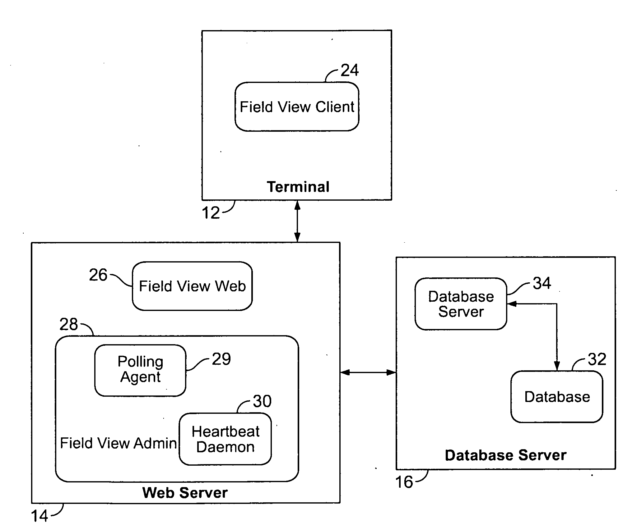
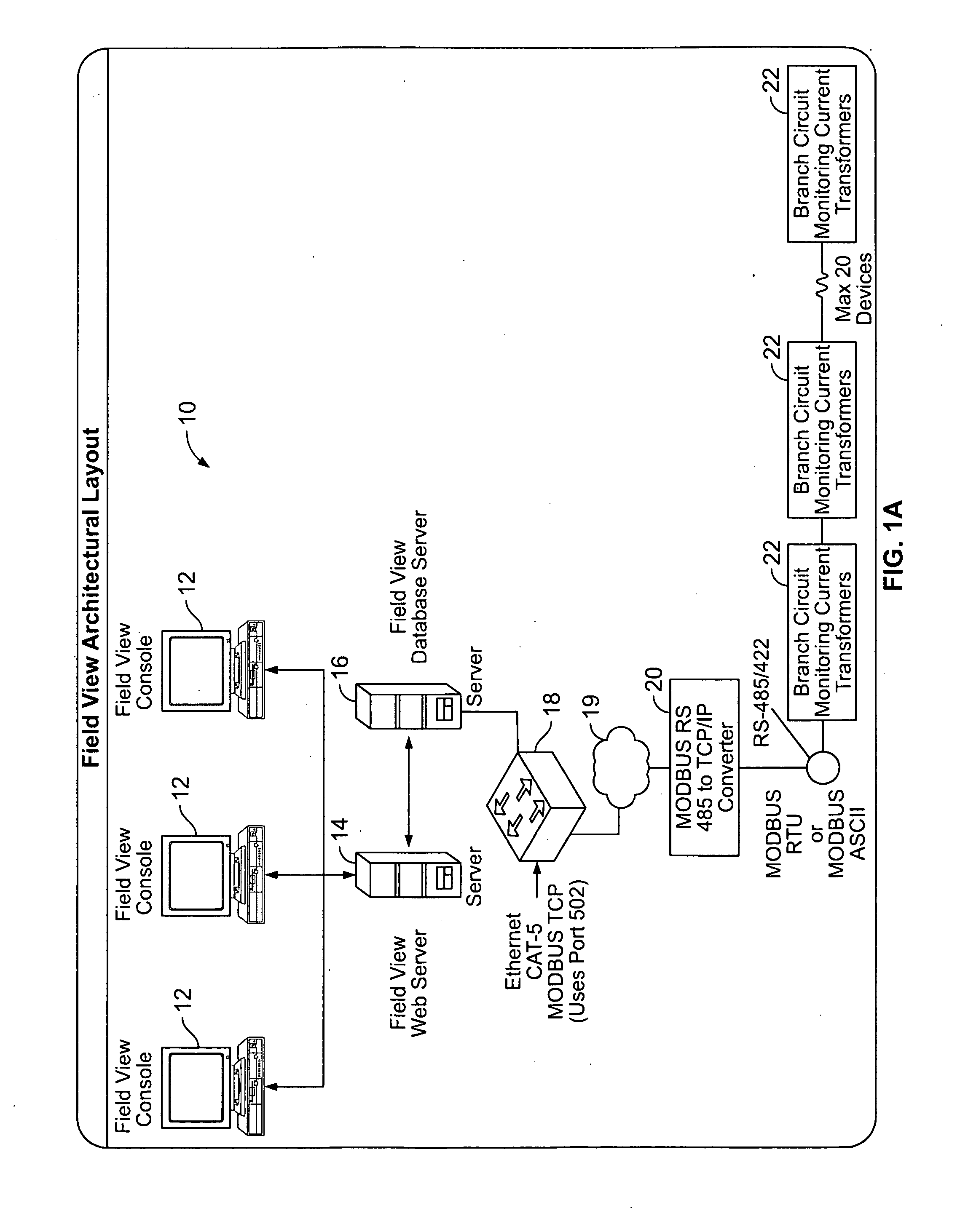
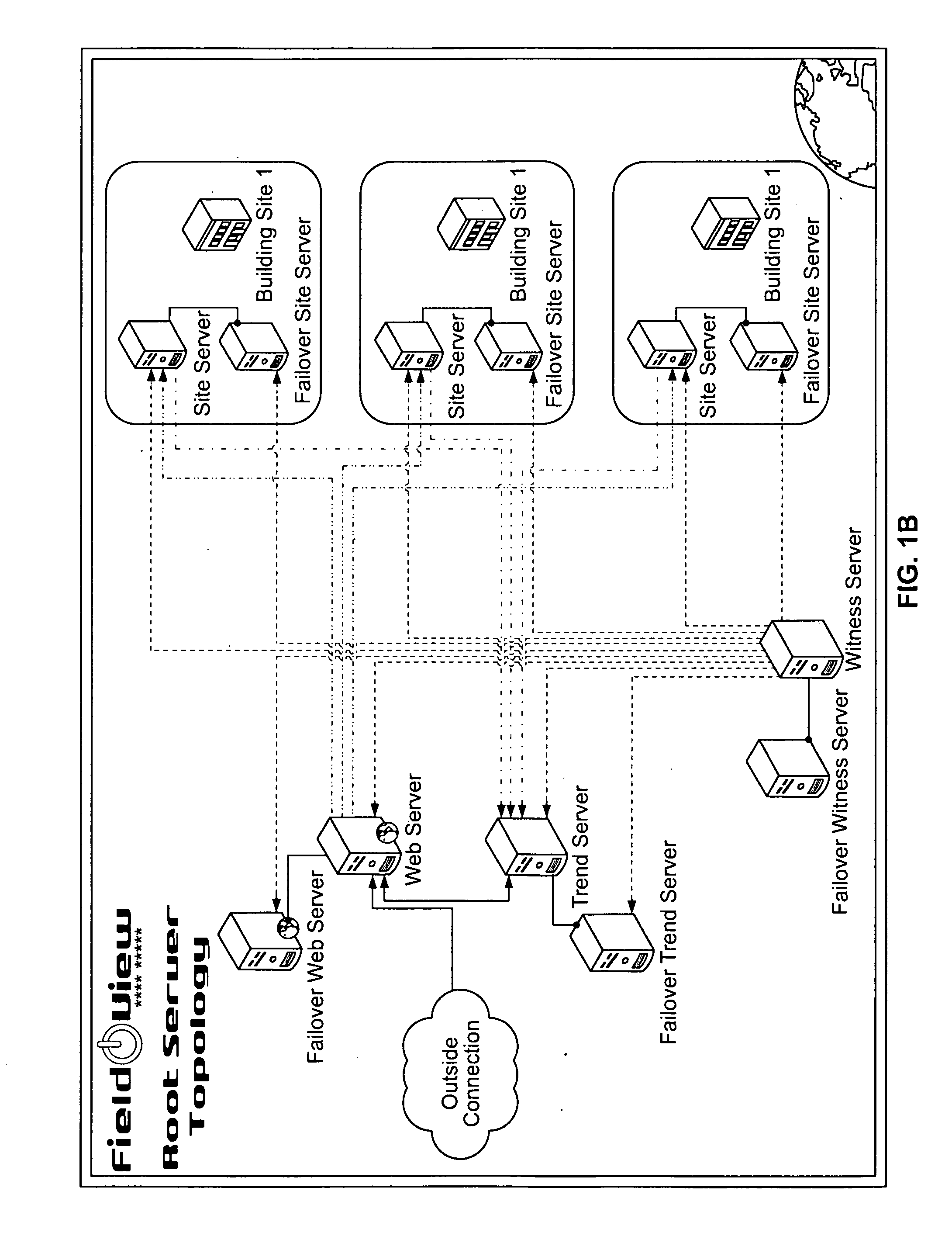
[0034]Embodiments of the present invention are directed to a system and method and software application that provides real time and historical branch circuit monitoring, circuit alarm notification, and cabinet asset management for small and large data centers. The system of the present invention makes it possible to view a plurality of data centers, which can be spread all over the world, as a single entity. The present system bridges the gap between facility infrastructure and cabinet management for power capacity planning. The system can display compiled energy usage data to allow for proper distribution of equipment in a data center to avoid overloading, of circuits and cabinets. An enterprise can predict alarms / excessive power dissipation conditions and make it possible for an enterprise to make decisions concerning load balance and upgrades to their systems based on power dissipation in a centralized fashion from any of a plurality of distributed terminals. Features of certain ...


PUM


Abstract

A system and method for monitoring, at a Web browser, electrical components can include the steps of receiving, information related to electrical components, such as servers, disposed in a plurality of cabinets, a portion of the cabinets being located in a first geographic location, and a second portion of the cabinets being located in a second geographic location, remote from the first geographic location, receiving information related to the real-time characteristics of the electrical components and displaying a graphical representation of the cabinets, the components and the information related to the real-time characteristics of the electrical components. The information related to the electrical components can include which cabinet the electrical components are located, the rated current draw of the electrical component, and the rated temperature of the electrical component. The real-time characteristics of the electrical components can include the actual percentage of rated current load, the actual percentage of rated temperature, and the actual percentage power draw. Displayed views can include a cabinet view, a room view, a floor view, a building view, a state view, a country view and a world view.

Description

CROSS REFERENCE TO RELATED APPLICATION[0001]This application claims the benefit of U.S. Provisional Patent application No. 60 / 913,313, filed Apr. 23, 2007, the contents of which are hereby incorporated by reference herein.FIELD OF THE INVENTION[0002]Embodiments of the invention relate generally to electrical systems, and more particularly to systems and methods for rack management and capacity planning for distributed electrical systems such as high-density server installations.BACKGROUND OF THE INVENTION[0003]In today's business environment, the success of many corporations and business enterprises is dependent upon a vast internal information technology infrastructure that includes hundreds or thousands of servers and other computer devices distributed throughout the enterprise.[0004]These servers are typically housed in special environmentally controlled rooms that contain rows of electrical cabinets. Each electrical cabinet can contain one or more servers, as well as electrical ...

Claims


Application Information

Patent Timeline
IPC IPC(8): G06F3/00
CPCH04L41/12H04L41/145H04L41/22H04L41/0686H04L43/065H04L43/0817H04L43/00
Inventor DIRLA, FRED
Owner FIELDVIEW SOLUTIONS
Learn More