Closing Method and Closing Machine

a technology of closing machine and closing method, which is applied in the direction of manufacturing tools, shaping tools, other domestic objects, etc., can solve the problems of reducing poor wear resistance of the die, and achieves the effects of improving production efficiency, high wear resistance, and greatly prolonging the life of the di

Inactive Publication Date: 2009-11-05
KYB CORP
View PDF15 Cites 4 Cited by
  • Summary
  • Abstract
  • Description
  • Claims
  • Application Information

AI Technical Summary

Benefits of technology

[0010]According to this invention, the die comprises the die main body that contacts the work piece and the holder that surrounds the die main body, the die main body is formed from a nonferrous metal, the holder is formed from a ferrous metal, and during a closing operation, the holder is subjected to induction heating by the high-frequency heating device whereas the die main body is heated by heat transfer from the holder. Hence, the die main body that is pressed against the work piece does not have to be subjected to induction heating through electromagnetic induction, and can be formed from a non-ferrous metal having high wear resistance. As a result, the life of the die can be greatly extended, and closing operations can be performed continuously over a long time period, enabling an improvement in production efficiency.

Problems solved by technology

However, the die used in this conventional closing machine is formed with a steel material such as hot die steel or the like, for example, as the material that is subjected to induction heating by the high-frequency heating device, and therefore the wear resistance of the die is poorer than that of a die formed from cemented carbide, for example, leading to a reduction in the life of the die.

Method used


Image

  • Closing Method and Closing Machine
  • Closing Method and Closing Machine
  • Closing Method and Closing Machine

Examples


Embodiment Construction

[0016]This invention will now be described in further detail with reference to the attached drawings.

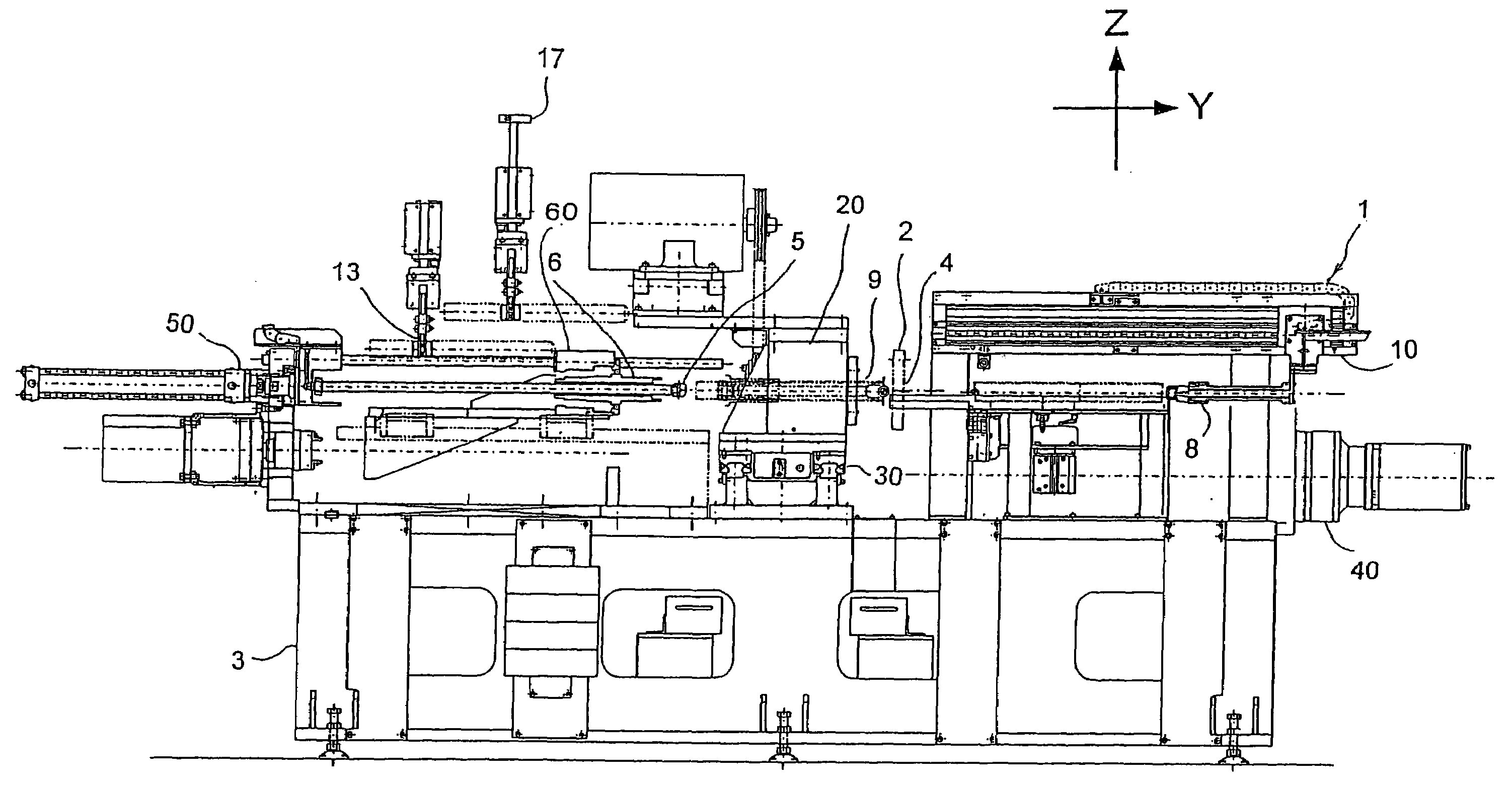
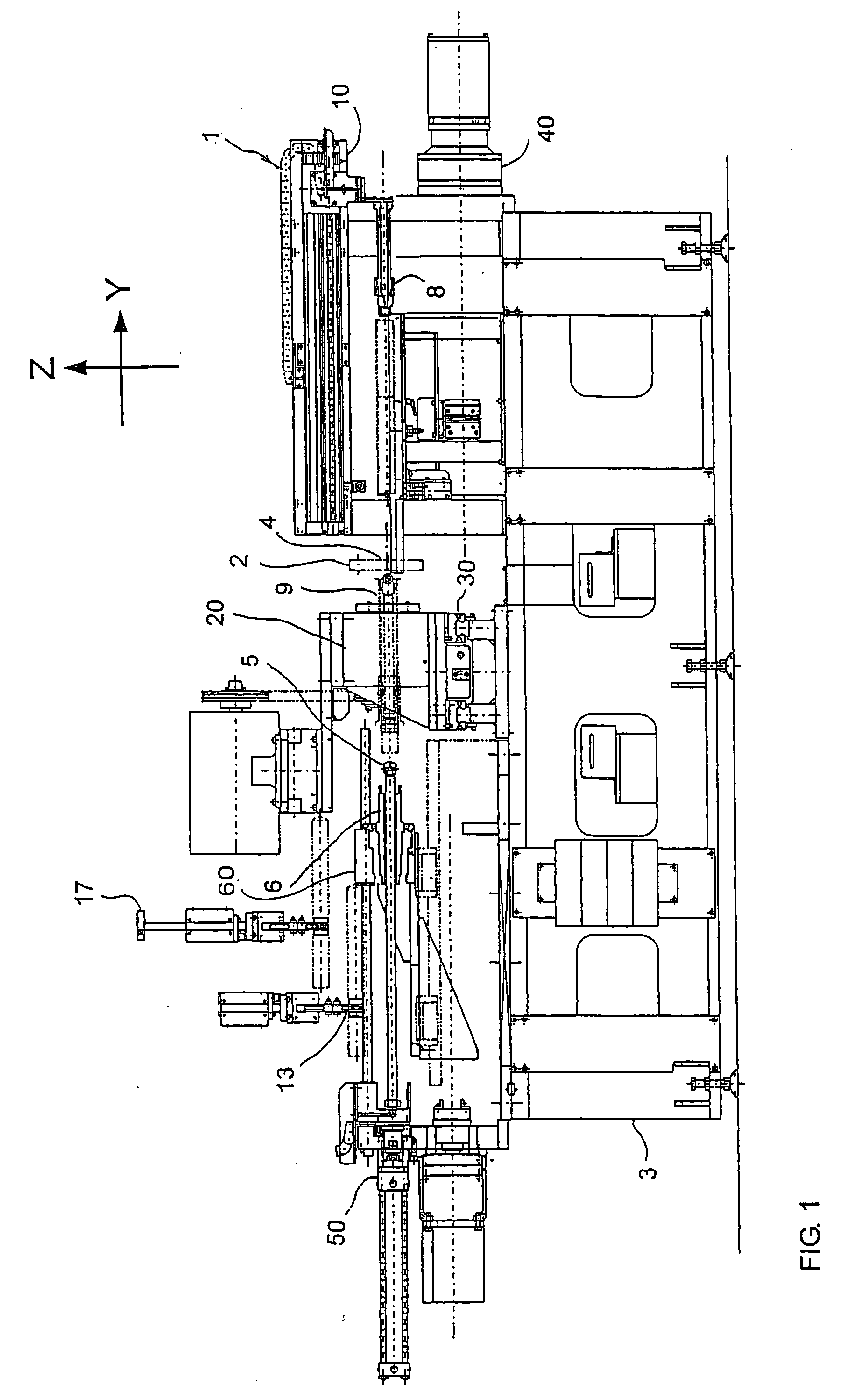
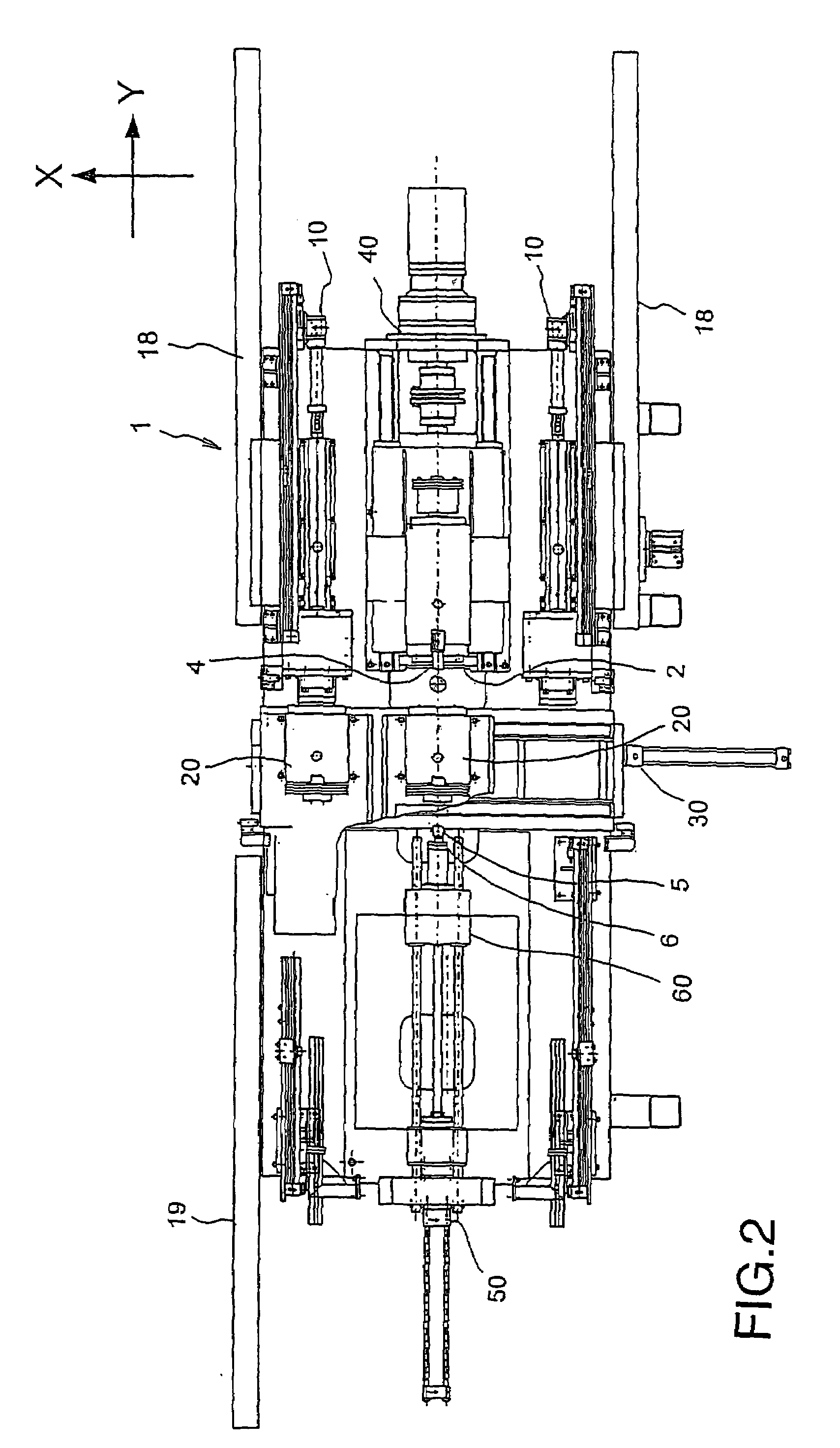
[0017]FIGS. 1 to 3 show the overall constitution of a closing machine 1. In FIGS. 1 to 3, three axes, namely X, Y, and Z, are set orthogonal to each other. It is assumed that the X axis extends in a substantially horizontal lateral direction, the Y axis extends in a substantially horizontal front-rear direction, and the Z axis extends in a substantially vertical direction. The overall constitution of the closing machine 1 will now be described.

[0018]Two chuck spindles 20 which drive a work piece 9 to rotate about its axial center, and a single die driving device 40 which drives a die 4, are provided in a central portion of the closing machine 1. The chuck spindles 20 perform a reciprocating motion in the X axis direction relative to a pedestal 3 via a chuck spindle moving device 30, to be described later, thereby moving alternately to the central portion of the closing machine 1 so a...


PUM

PropertyMeasurementUnit
temperatureaaaaaaaaaa
frequencyaaaaaaaaaa

Abstract

In a closing machine (1) for closing an open end of a work piece (9) by pressing a die (4) heated by a high frequency heating device (2) against the work piece (9) rotating about an axial center, the die (4) comprises a die main body (601) which contacts the work piece (9) and a holder (611) which surrounds the die main body (601). The die main body (601) is formed from cemented carbide whereas the holder (611) is formed from a steel material. The holder (611) is subjected to induction heating by the high-frequency heating device (2), whereas the die main body (601) is heated by heat transfer from the holder (611).

Description

FIELD OF THE INVENTION[0001]This invention relates to an improvement in a closing method and a closing machine for closing an open end of a metal pipe material.BACKGROUND OF THE INVENTION[0002]In a closing method, a work piece constituted by a metal pipe material is rotated and a die is pressed against the work piece while the work piece is heated. Thus, the work piece undergoes plastic deformation as it gradually approaches the die.[0003]A closing machine used in the closing operation comprises an outer diameter chuck that holds an outer peripheral surface of the work piece, and a chuck spindle that drives the outer diameter chuck to rotate together with the work piece. The work piece is closed by pressing the rotating die against the work piece at an offset to the rotating work piece.[0004]The closing method and closing machine described above are disclosed in JP2002-153930A.[0005]In a conventional closing machine, the die is subjected to induction heating using a high-frequency h...

Claims


Application Information

Patent Timeline
Patent Type & Authority Applications(United States)
IPC IPC(8): B21D7/00B21D37/16
CPCB21D37/16B21K21/14B21D41/04
Inventor HATTORI, TAIJI
Owner KYB CORP
Why Eureka
Try Eureka