Hydrocarbon recovery testing method

a technology of hydrocarbon recovery and testing method, which is applied in the direction of instruments, survey, borehole/well accessories, etc., can solve the problem that the distance between the two wells cannot be chosen arbitrarily, and achieve the effect of accurate assessment of efficacy and sufficient measurements

Active Publication Date: 2009-11-05
SCHLUMBERGER TECH CORP
View PDF15 Cites 23 Cited by
  • Summary
  • Abstract
  • Description
  • Claims
  • Application Information

AI Technical Summary

Benefits of technology

[0011]In a preferred variant of this aspect of the invention, the treated volume between the boreholes is optimized with regard to minimizing the duration and total cost of the test and at the same time performing the test in a volume of formation that is sufficiently large to be representative of heterogeneities in the larger reservoir. Thus, the distance between the two wells cannot be chosen arbitrarily small or large. The radial nature of the flow around the injector and around the producer well must also be taken into account. It is known that the average fluid velocity in a porous medium is inversely proportional to the distance r from the well, while at the same time having a large effect on an EOR recovery factor or recovery rate.
[0019]This embodiment has the advantage of providing sufficient measurements to observe heterogeneities within the formation and hence has the potential of delivering a more accurate assessment of the efficacy of the planned treatment within a larger section of the formation in a process which is referred to within the scope of the present invention as “upscaling” process.

Problems solved by technology

Thus, the distance between the two wells cannot be chosen arbitrarily small or large.

Method used


Image

  • Hydrocarbon recovery testing method
  • Hydrocarbon recovery testing method
  • Hydrocarbon recovery testing method

Examples


Embodiment Construction

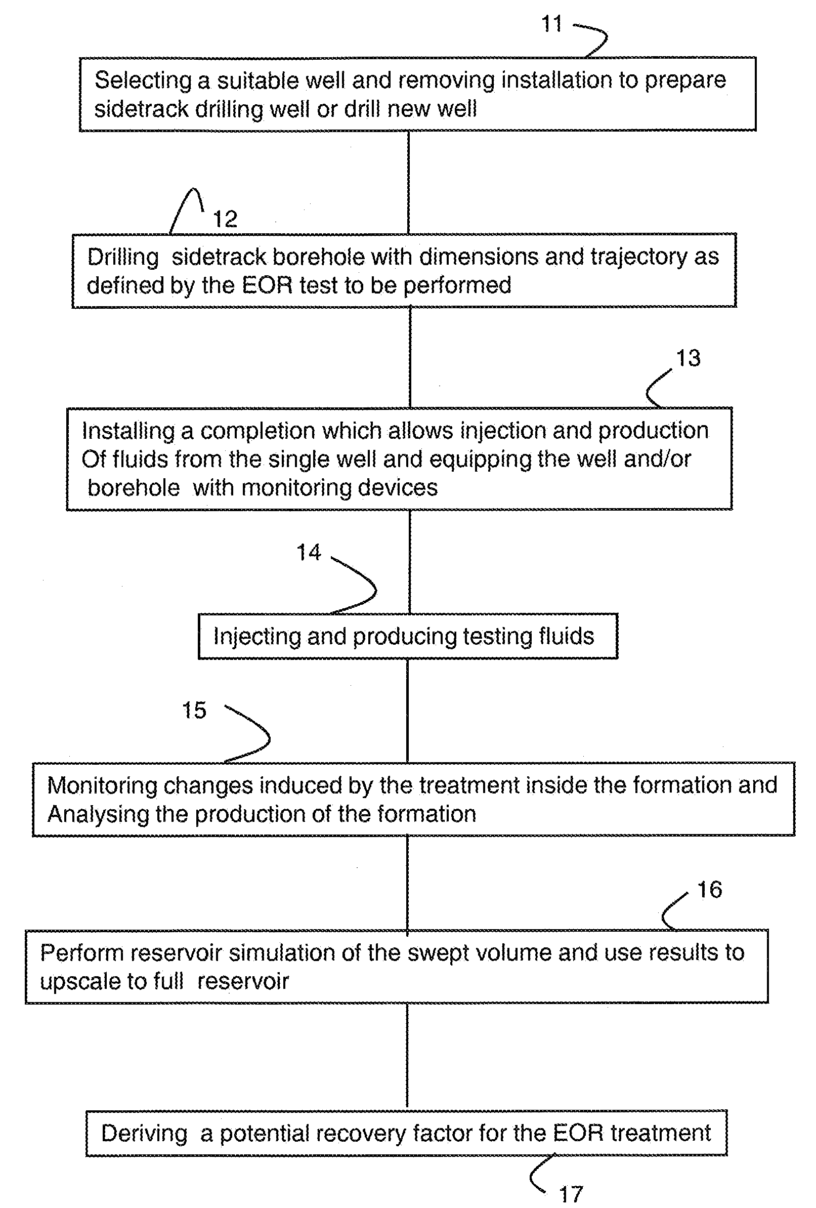
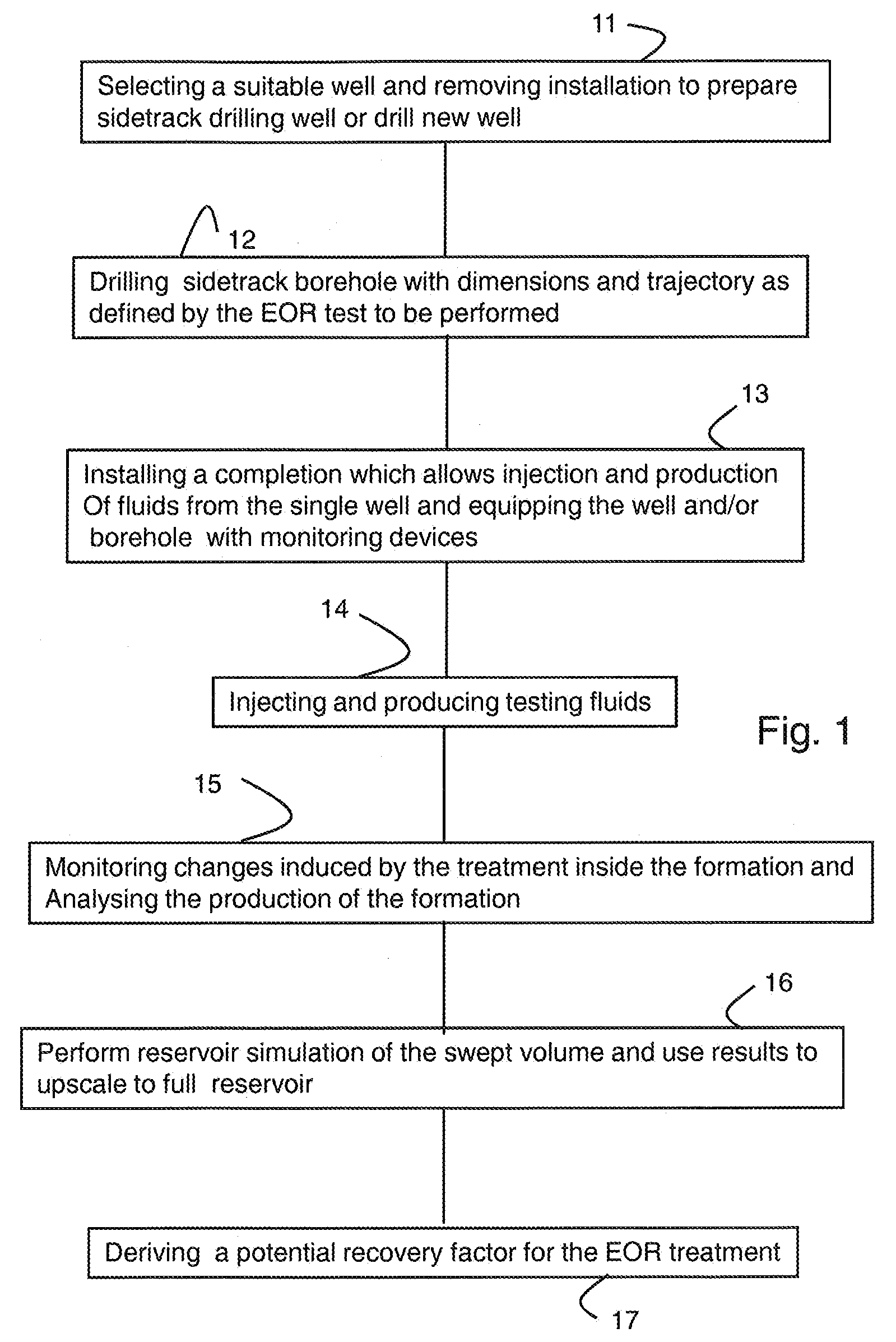
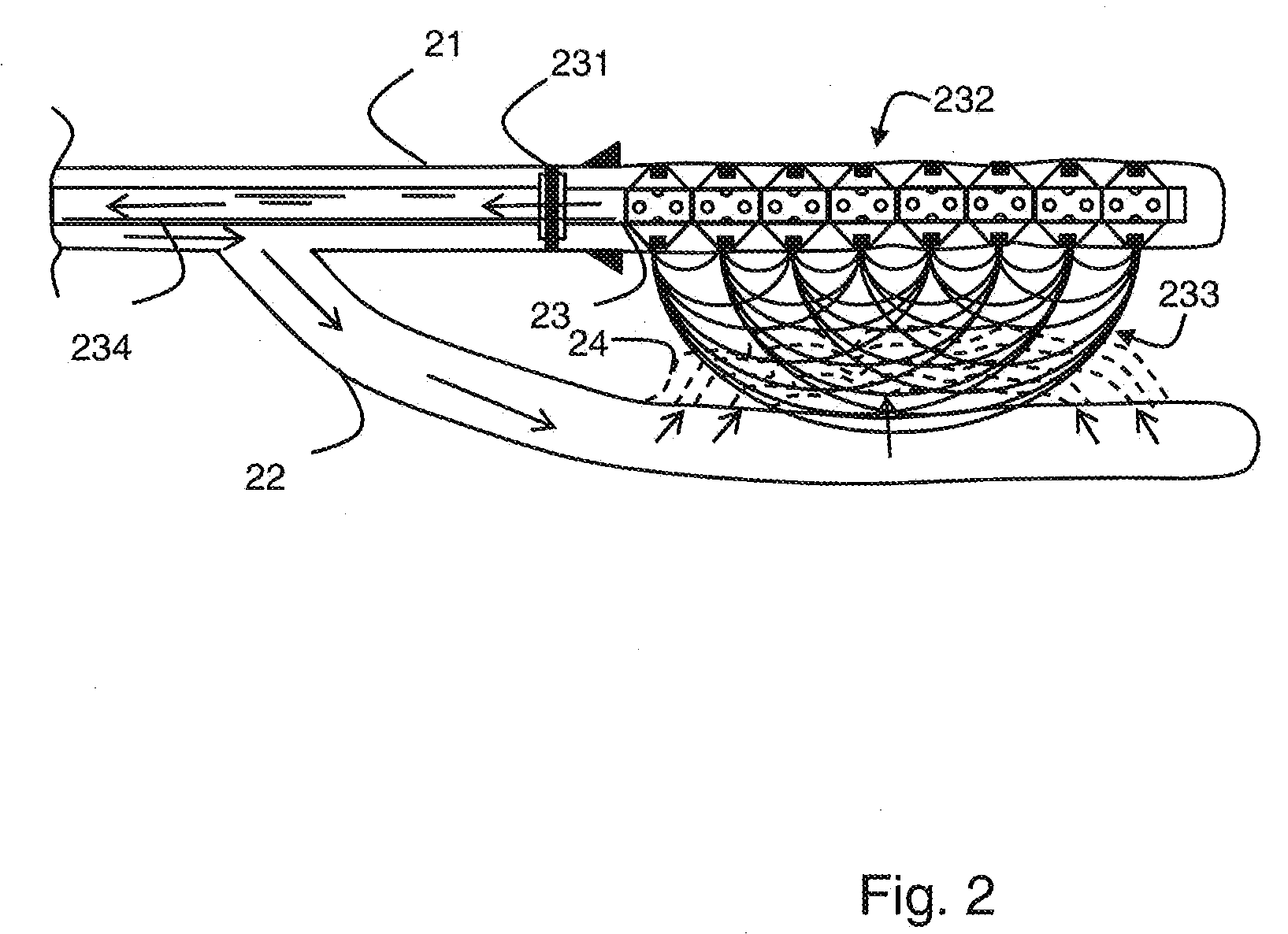
[0028]The following example describes a method in accordance with one embodiment of the present invention using the block diagram of FIG. 1 and the drawing of FIG. 2. The example is based on the presence of an existing well.

[0029]In a first step 11, an existing well 21 is selected. The selection process is important as some of the measurements described below can be simplified through a good choice of a well. It is advantageous to select an old producing well in a zone completely swept, e.g., after water breakthrough. Typically the residual oil saturation around an injector well is not representative of the remaining oil saturation in most parts of a swept zone. The oil recovery achieved at this stage of the life of a producing well is close to the maximum reachable under plain sea-water injection or whatever injection fluid was used. Testing the EOR treatment as described below then provides a direct quantitative measurement of the incremental oil recovery that can be obtained by t...


PUM


Abstract

A method of testing the response of a subterranean formation to a formation treatment is described including the injection of a treatment fluid and the production of formation fluids from two separate boreholes or two boreholes from a single well such that the treatment fluid sweeps the formation between the two boreholes, and the use of downhole monitoring devices to determine a volume swept by the treatment fluid.

Description

FIELD OF THE INVENTION[0001]The invention relates to a method of testing formation treatments used to recover hydrocarbons from subterranean formations and other related treatments. More specifically, the invention pertains to methods of screening and evaluating enhanced oil recovery (EOR) treatments between closely spaced wells or between laterals branching off a single well.BACKGROUND[0002]As hydrocarbon fields are growing more mature, the established methods of producing oil are no longer sufficient to exploit a reservoir to the extent theoretically possible. In response to this challenge a plethora of new methods have been proposed to increase recovery beyond that afforded by established methods. These methods are generally referred to as “Enhanced Oil Recovery” or EOR treatments.[0003]Many EOR treatments make use of the injection of heat in form of heated fluids, the injection of gas (Methane, Nitrogen, Carbon Dioxide, etc.) together or alternating with water injection, or the ...

Claims


Application Information

Patent Timeline
Patent Type & Authority Applications(United States)
IPC IPC(8): E21B47/00E21B43/16E21B43/25
CPCE21B43/16
Inventor MONTARON, BERNARD
Owner SCHLUMBERGER TECH CORP
Why Eureka
Try Eureka