Tension guardrail terminal

a guardrail terminal and tension technology, applied in roadway safety arrangements, roadways, construction, etc., to achieve the effect of dissipating impact energy, dissipating impact energy of a vehicle colliding, and releasing tension

Active Publication Date: 2009-11-05
TEXAS A&M UNIVERSITY
View PDF35 Cites 10 Cited by
  • Summary
  • Abstract
  • Description
  • Claims
  • Application Information

AI Technical Summary

Benefits of technology

[0008]Technical advantages of particular embodiments of the present invention include a guardrail end treatment that dissipates impact energy through the compression of a W-beam guardrail element. Thus, one advantage may be that the guardrail end treatment is energy absorbing. Another advantage may be that the end treatment forces the W-beam guardrail element through a flattening structure that squeezes the guardrail into a relatively flat plate. Specifically, the guardrail end treatment may dissipate impact energy of a vehicle colliding with an end of a guardrail by flattening a portion of the guardrail.
[0009]Still another advantage may be that an end of the W-beam guardrail element extends through the flattening structure and tapers to the ground. The W-beam guardrail element may be secured to the ground in tension. The components of the system that provide the tensile connection of the guardrail beam to the terminal support post may enable the guardrail beam to remain secured after an end-on or re-directive impact. Thus, the system may remain in tension during both types of impacts. Still another advantage may be that the tension is released when the system is impacted in the reverse direction near the terminal end, however. The releasing of tension in the guardrail element for reverse direction impacts prevents vehicle instability and excessive deceleration.

Problems solved by technology

Specifically, the guardrail end treatment may dissipate impact energy of a vehicle colliding with an end of a guardrail by flattening a portion of the guardrail.

Method used


Image

  • Tension guardrail terminal
  • Tension guardrail terminal
  • Tension guardrail terminal

Examples


Embodiment Construction

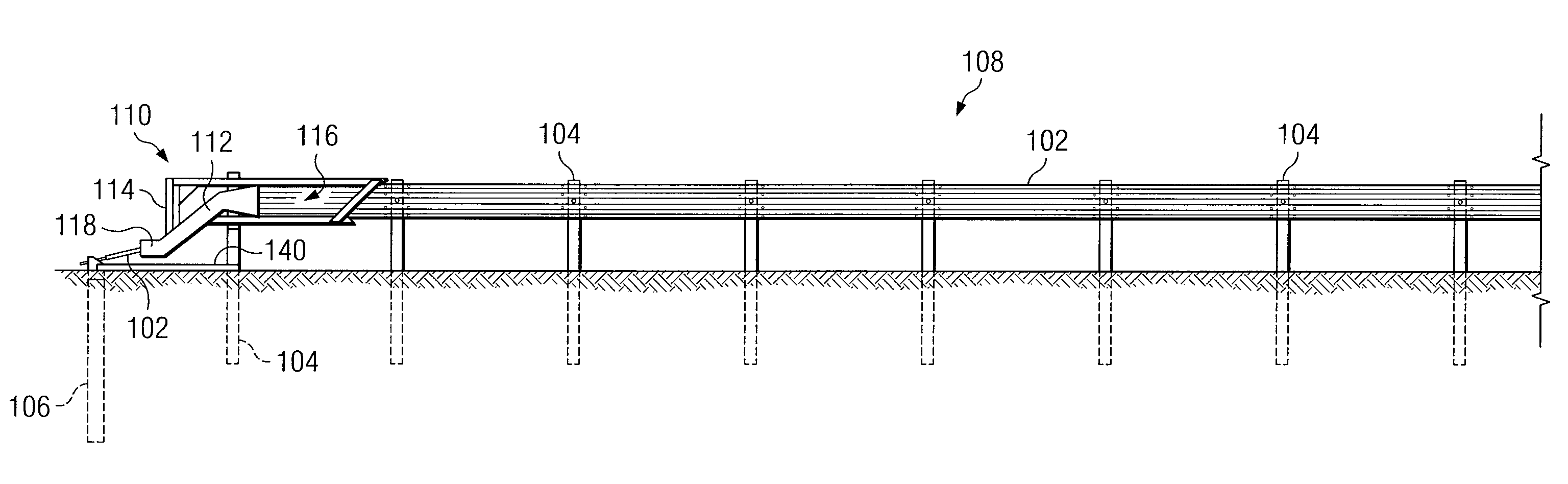
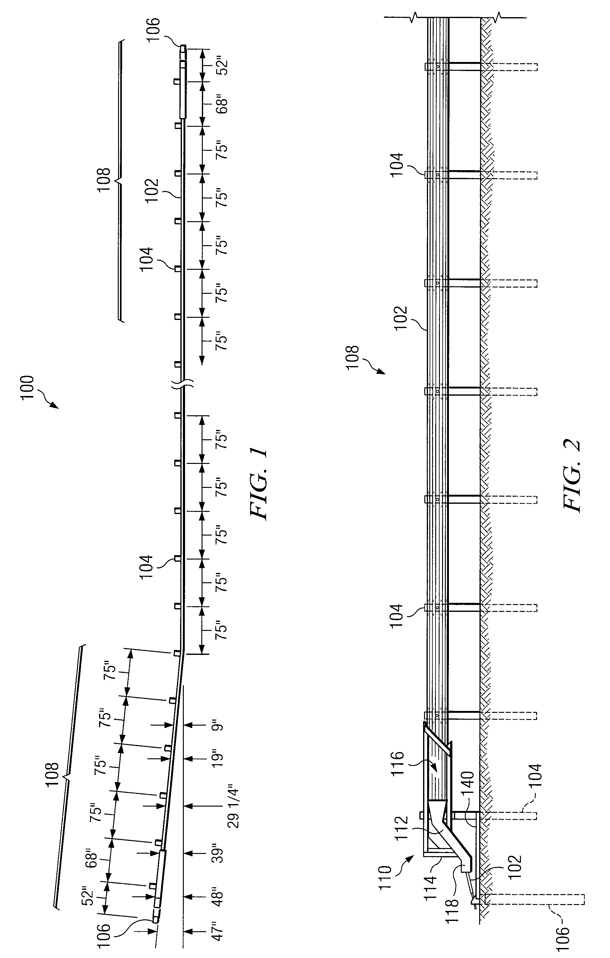
[0023]Existing guardrail end treatments have proven to be unsafe for some collision conditions that happen on the highway, sensitive to installation details, and / or very costly. However, the end treatment described below is a safety treatment for the ends of a W-beam guardrail that provides a higher level of performance over a wider range of collision conditions and reduces end treatment costs and the number of injuries and deaths associated with guardrail terminal accidents. The described system maintains the tension in the guardrail beam element during both end-on and re-directive type impacts. When the system is impacted in the reverse direction near the terminal end, however, the anchorage system may release to prevent vehicle instability or excessive deceleration.

[0024]FIG. 1 illustrates a guardrail safety system 100 that incorporates certain aspects of the present invention. Guardrail system 100 may be installed adjacent a roadway, to protect vehicles, drivers and passengers f...


PUM


Abstract

In accordance with a particular embodiment of the present invention, a terminal portion of a guardrail safety system includes a terminal portion of a guardrail beam having a downstream end and upstream end. The terminal portion of the guardrail beam slopes from a height appropriate for redirecting an errant vehicle to a height proximate the surface of the ground at an upstream end of the terminal portion. Support posts are installed adjacent a roadway in spaced apart relation to one another and are coupled to the terminal portion of the guardrail beam. A terminal support post is installed adjacent the roadway at an upstream end of the end terminal. The terminal support post couples to an upstream end of the terminal portion of the guardrail beam by a resistive, tensile coupling that maintains tension in the terminal portion of the guardrail beam. The resistive, tensile coupling is maintained between the terminal support post and the guardrail beam during an end-on or re-directive impact by a vehicle. However, the resistive, tensile coupling between the terminal support post and the guardrail beam is released during a reverse-direction impact.

Description

TECHNICAL FIELD[0001]The present invention relates generally to safety treatment for the ends of W-beam guardrails; and more particularly, to a tensioned guardrail terminal for dissipating impact energy of a car colliding with the end of the W-beam guardrail in an end-on or re-directive impact.BACKGROUND[0002]Along most highways there are hazards that can be a substantial danger to drivers of automobiles if the automobiles leave the highway. To reduce the severity of accidents due to vehicles leaving a highway, guardrails are provided. The guardrails are installed such that the beam elements are in tension to aid in re-directive type impacts. Guardrails must be installed, however, such that the terminal end of the guardrail facing the flow of traffic is not a hazard. Early guardrails had no proper termination at the ends, and it was not uncommon for impacting vehicles to become impaled on the guardrail causing intense deceleration of the vehicle and severe injury to the occupants. I...

Claims


Application Information

Patent Timeline
Patent Type & Authority Applications(United States)
IPC IPC(8): E01F15/00
CPCE01F15/143
Inventor ABU-ODEH, AKRAM Y.ALBERSON, DEAN C.BLIGH, ROGER P.BULLARD, JR., D. LANCEBUTH, C. EUGENE
Owner TEXAS A&M UNIVERSITY
Why Eureka
Try Eureka