

Display
a display device and primary color technology, applied in static indicating devices, cathode-ray tube indicators, instruments, etc., can solve the problems of the display quality decline of the display device that uses the four primary colors, and achieve the effect of high color temperature and wide color reproduction rang
- Summary
- Abstract
- Description
- Claims
- Application Information
AI Technical Summary
Benefits of technology
Problems solved by technology
Method used
Image

Examples
first preferred embodiment
[0061]Hereinafter, a first preferred embodiment of a display device according to the present invention will be described with reference to the accompanying drawings.
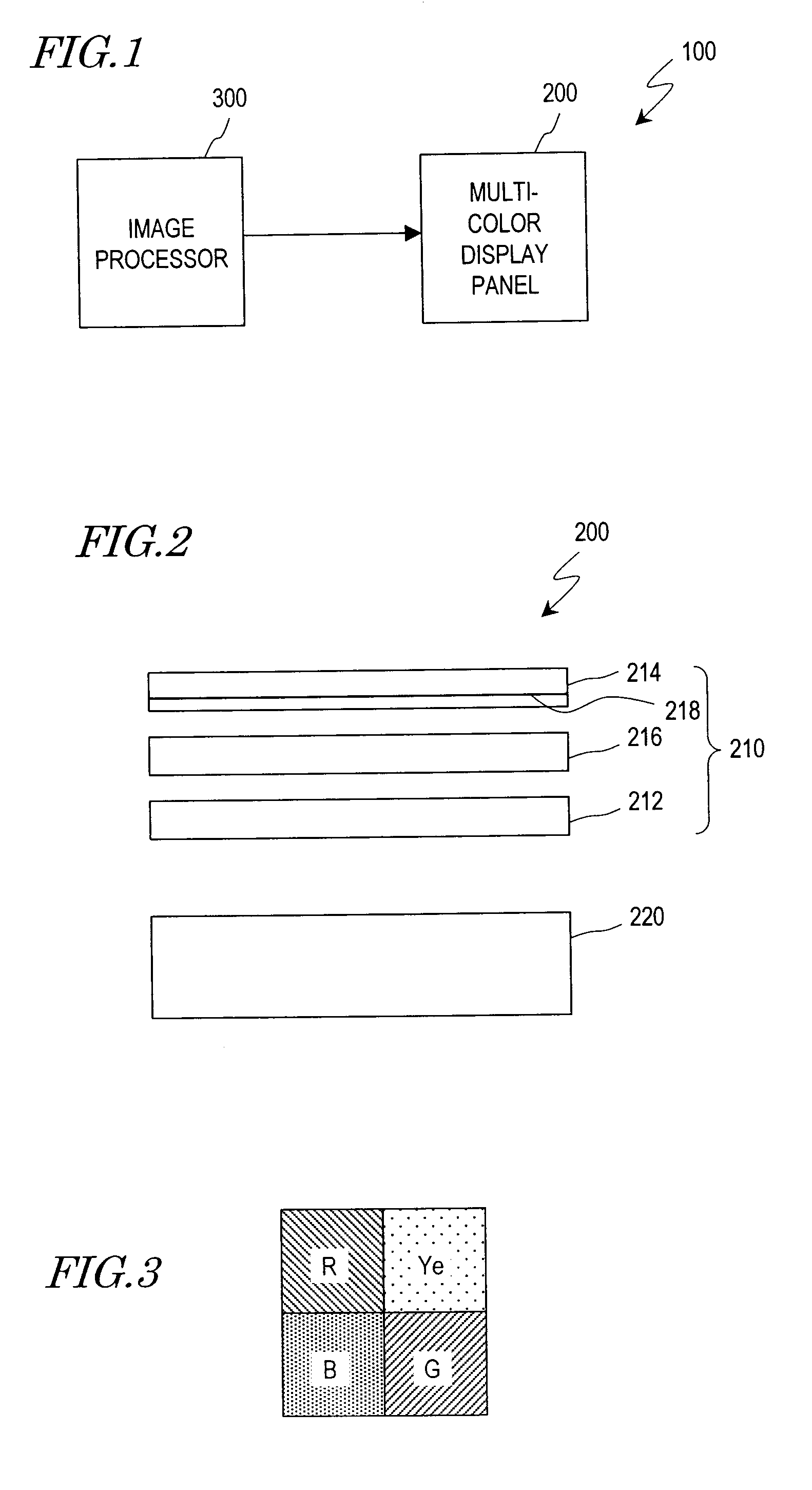
[0062]FIG. 1 is a block diagram schematically showing the configuration of a display device 100 of this preferred embodiment. As shown in FIG. 1, the display device 100 includes a multi-color display panel 200 and an image processor 300 for generating a signal to be supplied to the multi-color display panel 200. The multi-color display panel 200 may be an LCD panel, for example.
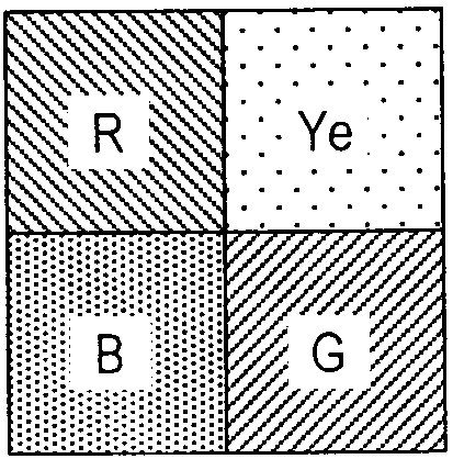
[0063]In the display device 100 of this preferred embodiment, the multi-color display panel 200 includes a display unit 210 and a backlight 220 as shown in FIG. 2. The display unit 210 includes an active-matrix substrate 212, a counter substrate 214 and a liquid crystal layer 216, which is sandwiched between the active-matrix substrate 212 and the counter substrate 214. Color filters 218 are arranged on the counter substrate 214. LEDs are used as ...
second preferred embodiment
[0132]The display device of the first preferred embodiment described above uses the similar backlight 220 as that of a conventional LCD. However, the present invention is in no way limited to that specific preferred embodiment.
[0133]Hereinafter, a second preferred embodiment of a display device according to the present invention will be described with reference to the accompanying drawings. The display device 100 of this preferred embodiment has the similar configuration as the counterpart of the first preferred embodiment that has already been described with reference to FIGS. 1, 2 and 8 except that the backlight 220 emits radiation with a different spectrum. Thus, the repeated description thereof is omitted to avoid redundancies.
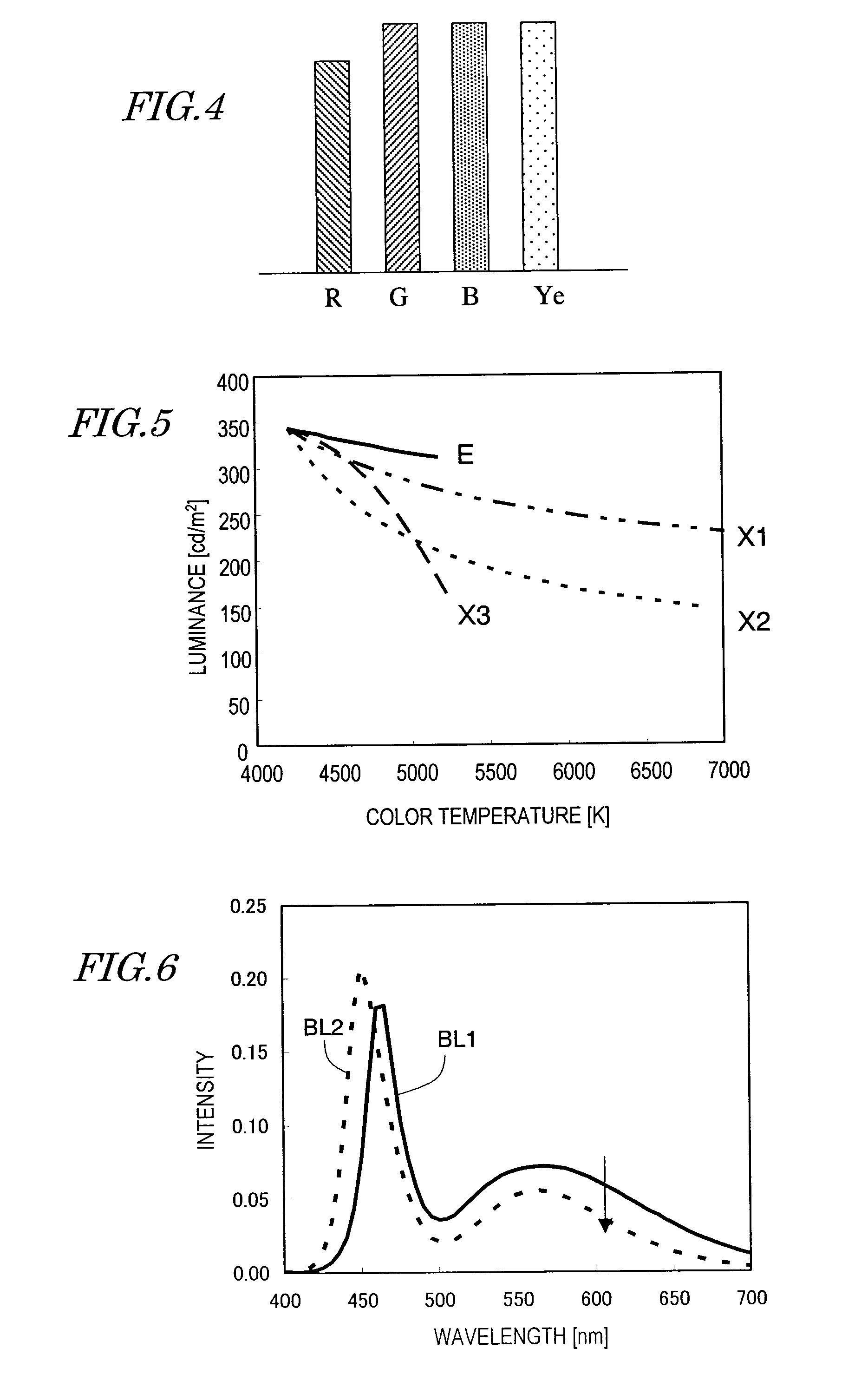
[0134]FIG. 12 is a graph showing the spectrum of the radiation that was emitted from the backlight 220 of the display device 100 of this preferred embodiment. The backlight 220 for the display device 100 of this preferred embodiment emits light, of which t...
third preferred embodiment
[0148]Hereinafter, a third preferred embodiment of a display device according to the present invention will be described with reference to the accompanying drawings.
[0149]The display device 100 of this preferred embodiment has a similar configuration as that of the counterparts of the first and second preferred embodiments that have already been described with reference to FIGS. 1, 2 and 8 except that the backlight 220 emits radiation with a different spectrum. Thus, the repeated description thereof is omitted to avoid redundancies.
[0150]FIG. 14 is a graph showing the spectrum of the radiation that was emitted from the backlight 220 of the display device 100 of this preferred embodiment. The backlight 220 for the display device 100 of this preferred embodiment emits light, of which the intensity at a wavelength associated with blue is even higher, and the intensities at wavelengths associated with the colors green and red are even lower, than those of the light emitted from the back...
PUM
 Abstract
Description
Claims
Application Information