
Image processing apparatus and image encoding method

a technology of image processing and image object, applied in the field of image processing apparatus, can solve the problems of low compression ratio, increase of difference from original image, poor quality of decoded characters, etc., and achieve the effect of improving the compression ratio of document image and improving the quality and reusability of image objects

Active Publication Date: 2009-11-05
CANON KK
View PDF9 Cites 31 Cited by
  • Summary
  • Abstract
  • Description
  • Claims
  • Application Information

AI Technical Summary

Benefits of technology

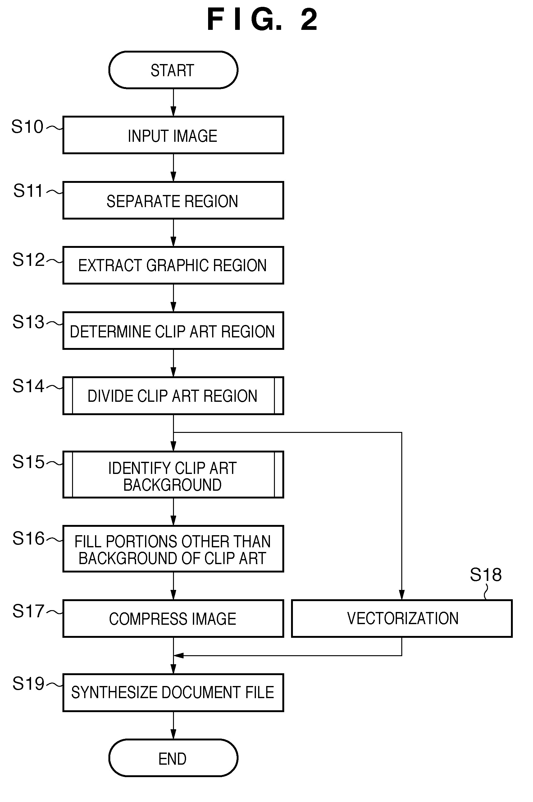
The present invention provides an image processing apparatus and method that can increase the compression ratio of a document image with non-photo image regions and improve the quality and reusability of image objects when reproduced. The apparatus can identify non-photo image regions, encode them through a vectorization process, and fill in the background region with a color of the non-photo image region. The result is a high-quality document image that can be easily compressed and reused.

Problems solved by technology

However, when a document image including both a character region and a photo image region is compressed at a compression ratio suitable for the character region (e.g., lossless compression), a problem arises in that although the image quality after decoding is good, the compression ratio is low.
On the other hand, when the document image is compressed at a compression ratio suitable for the photo image region (e.g., lossy compression such as JPEG), a problem arises in that although a high compression ratio is achieved, the quality of decoded characters is poor.
Specifically, when the background portion with such color gradation is treated as having a single color, the difference from the original image increases, causing a strong sense of discomfort.
In this case, a problem arises in that part of the photo image region overlapping the non-photo image region disappears as shown in FIG. 17 because the whole non-photo image region is filled, making it impossible to reproduce the original image.

Method used


Image

  • Image processing apparatus and image encoding method
  • Image processing apparatus and image encoding method
  • Image processing apparatus and image encoding method

Examples


embodiment 1

Configuration of Apparatus

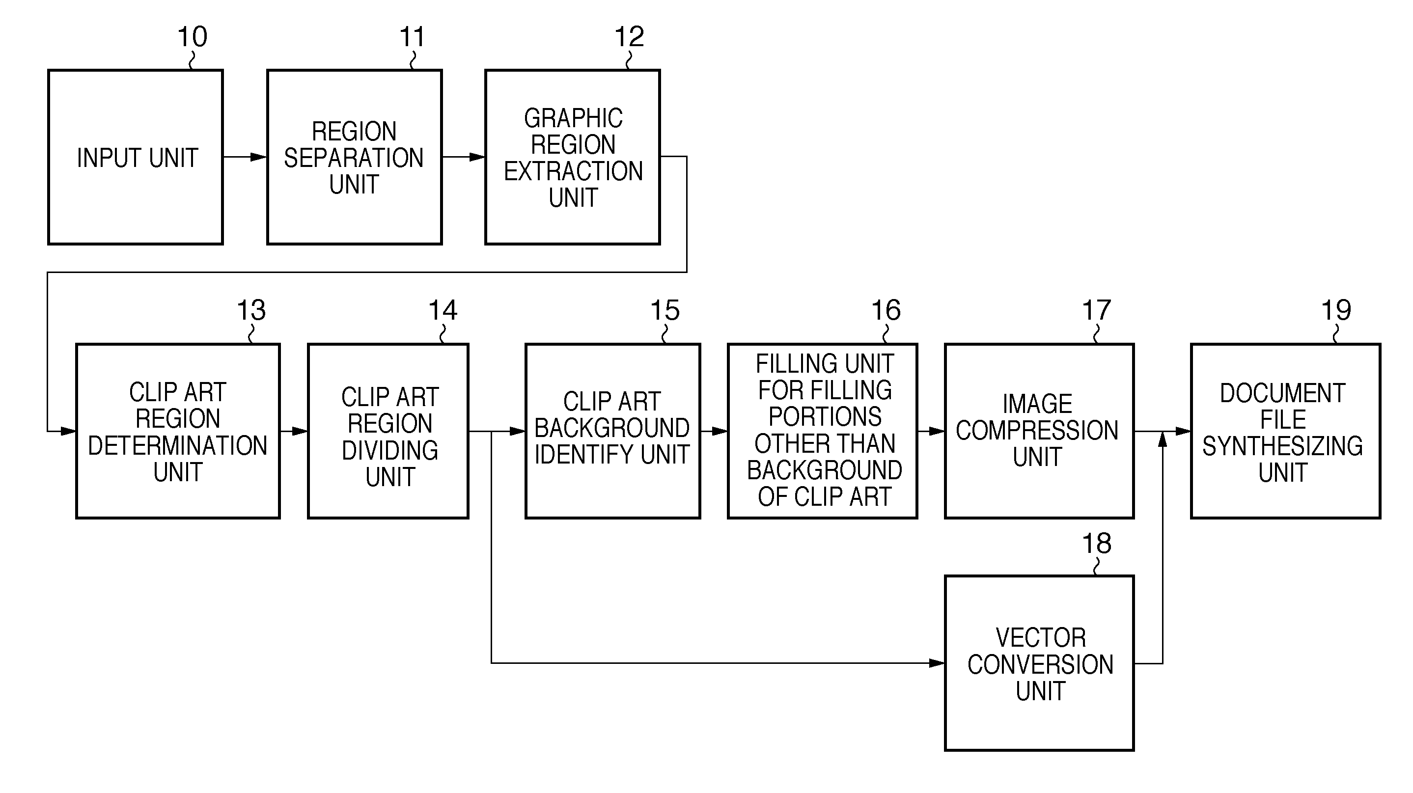
[0041]FIG. 1 is a block diagram illustrating the configuration of an image processing apparatus that has a function for performing a process for filling a non-photo image region and a process for generating a synthesized document file according to Embodiment 1 of the present invention. As used herein, “synthesized document file” refers to a document file in which a photo image portion has been compressed in a format such as JPEG, and characters and a non-photo image have been vectorized and compressed. In other words, it can be said that this apparatus is an apparatus that executes an image encoding method. In FIG. 1, an input unit 10 is a unit that inputs paper information as a color document image through scanning, and a region separation unit 11 is a unit that separates the color document image into a plurality of types of regions such as a character region, a graphic region, and a line drawing region. Through the region separation process, an attribute ...

embodiment 2

[0074]A process for identifying the background region and filling the same performed when a clip art region partially overlaps another region such as a photo will be described as Embodiment 2.

[0075]FIG. 15 is a diagram illustrating an example in which a clip art region is selected from a document image. In the document image shown in FIG. 15, a photo image region 31 is overlapping a clip art region 33. If the filling process is performed on the whole clip art region, part of the photo image region overlapping the clip art region is filled as shown in FIG. 17. To address this, in the present embodiment, after the clip art region is clustered in colors, a cluster corresponding to the background region is identified in the same manner as in Embodiment 1, and then a determination is made as to whether or not a photo image region is overlapping. If it is determined that a photo image region is overlapping, a cluster corresponding to the position of the overlapping portion is also identif...

embodiment 3

[0077]Embodiment 1 utilized the cluster information of the pixels located on the sides of a clip art region to identify the background of the clip art, whereas Embodiment 3 focuses on the pixels located in a partial region (near a corner, near the center of a side) of a clip art region, utilizes the cluster information of these pixels, and identifies a cluster having the highest frequency as the background cluster.

[0078]In the present embodiment, in order to identify the background region, in a clip art (non-photo image) region, sample regions are defined to include a side (end portion) of the non-photo image region, and a cluster to which a largest number of pixels of the sample regions belong is identified as the background region.

CLIP ART BACKGROUND IDENTIFYING PROCESS EXAMPLE 1

[0079]FIG. 19 shows an example of a clip art region. It is assumed here that this clip art image has been divided into four regions through a region division process: a green cluster 20010, a yellow cluste...


PUM


Abstract

A region separation unit separates an inputted color document image into a plurality of types of regions such as a character region, a clip art region and a photo image region, and a clip art region extraction unit identifies the clip art region from among the separated regions. A clip art region dividing unit divides the clip art region based on the color features of the clip art region, and a clip art background identify unit identifies the background portion of the clip art region from among the divided regions. A filling unit for filling portions other than the background of a clip art fills a portion of the clip art other than the background with the background color, and a JPEG compression unit compresses the result obtained from the process for filling a clip art portion.

Description

BACKGROUND OF THE INVENTION[0001]1. Field of the Invention[0002]The present invention relates to an image processing apparatus that compresses document images and an image encoding method, and more particularly to an image processing apparatus that compresses a document image including a non-photo image and an image encoding method.[0003]2. Description of the Related Art[0004]Along with the recent digitization of information, rather than storing paper documents, systems are becoming widely available that digitize information through scanning using a scanner or the like, and transmit / receive the electronic data to / from other apparatuses. In order to reduce the cost required for transmission and reception, compressing digitized documents at high ratios is in demand. At the same time, reusability, which is the ability to partially edit the digitized data, as well as the ability to achieve high image quality while preventing degradation of the image quality even when images are enlarged...

Claims


Application Information

Patent Timeline
Patent Type & Authority Applications(United States)
IPC IPC(8): G06K9/34G06K9/36
CPCG06K9/00456G06V30/413
Inventor DAI, XIAOYAN
Owner CANON KK
Learn More