Shooting pot for feeding multiple nozzles

Inactive Publication Date: 2009-11-05
HUSKY INJECTION MOLDING SYST LTD
View PDF11 Cites 28 Cited by
  • Summary
  • Abstract
  • Description
  • Claims
  • Application Information

AI Technical Summary

Benefits of technology

[0011]The present invention provides an injection apparatus capable of injecting melt into a mold cavity at high pressure while utilizing a low pressure injection unit and

Problems solved by technology

These high pressure injection units and manifold systems are often more expensive and more difficult to maintain because higher quality materials capable of withstanding high pressures must be used.
These systems a

Method used


Image

  • Shooting pot for feeding multiple nozzles
  • Shooting pot for feeding multiple nozzles
  • Shooting pot for feeding multiple nozzles

Examples


Embodiment Construction

[0023]The following description of the preferred embodiment(s) is merely exemplary in nature and is in no way intended to limit the invention, its application, or uses.

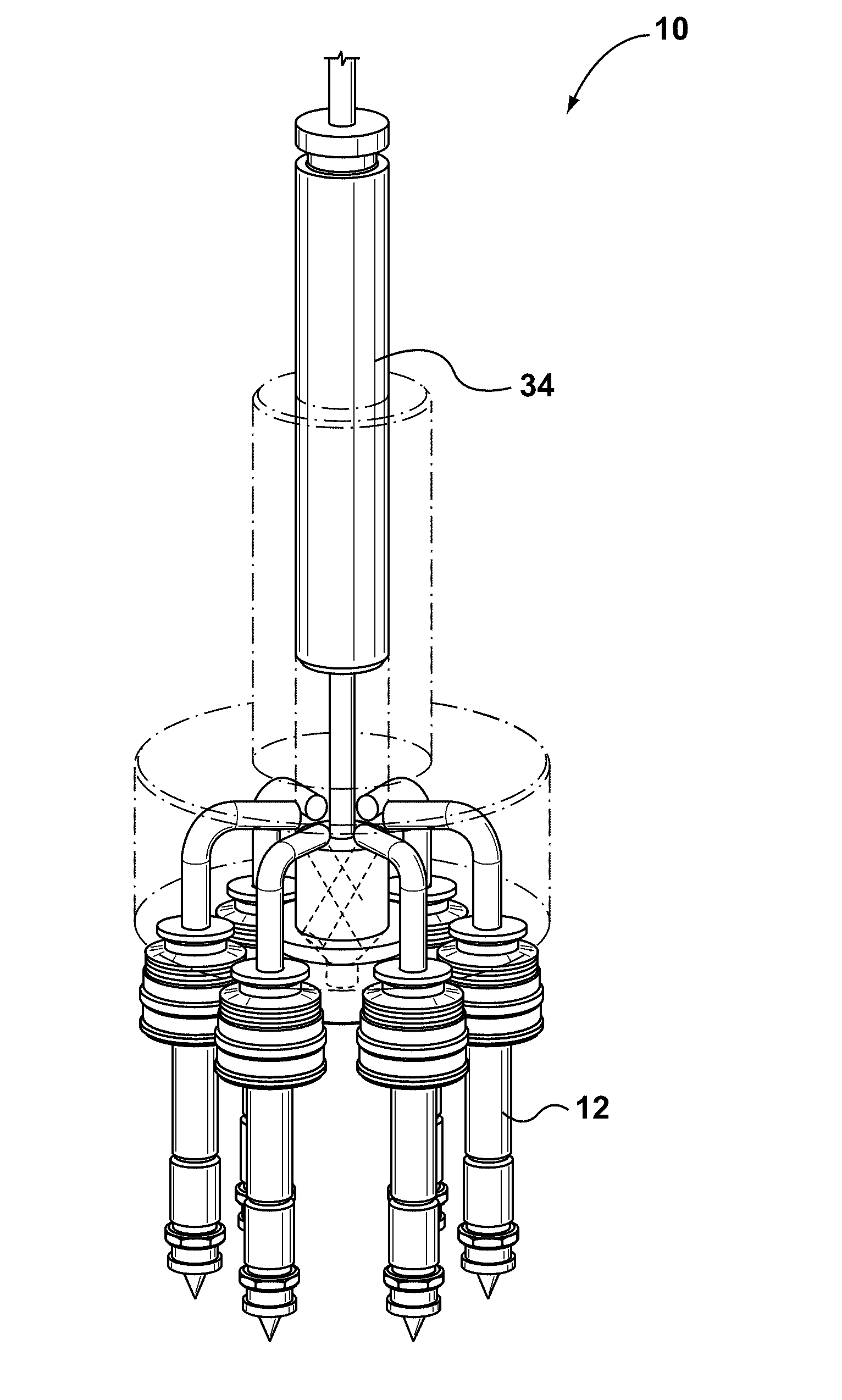
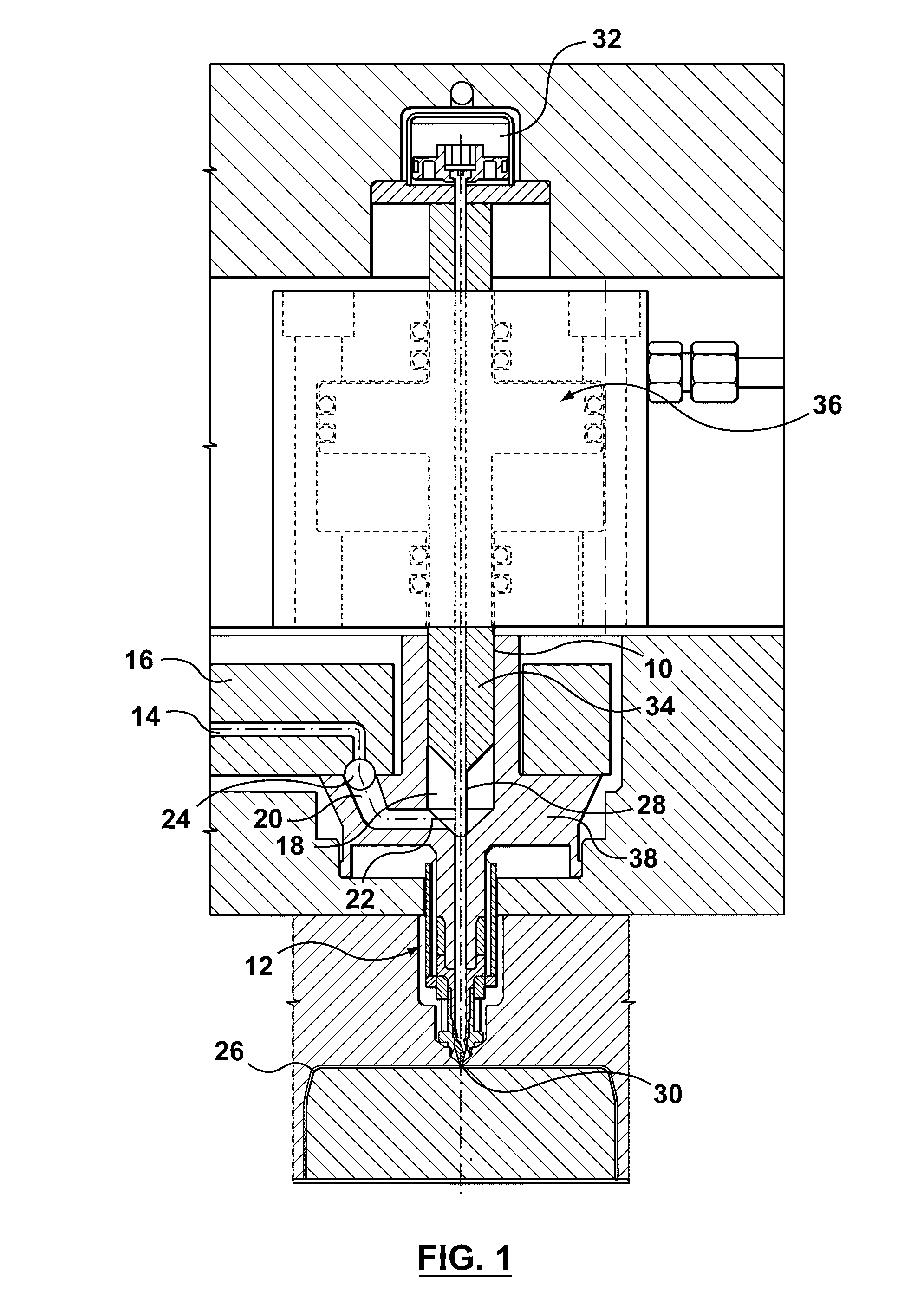
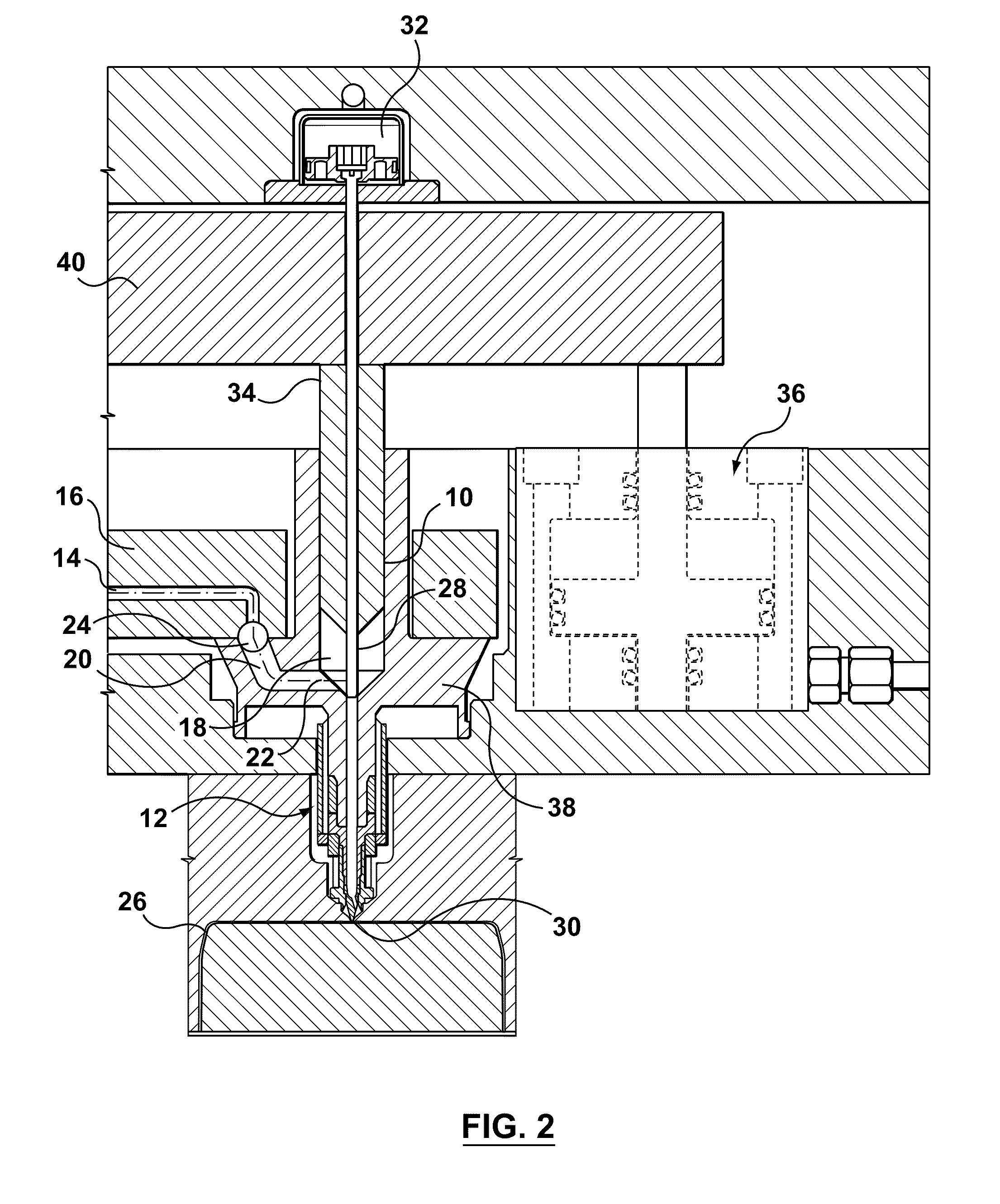
[0024]As illustrated in FIG. 1, a hot runner system for injection molding is provided having a shooting pot assembly10 contained within a nozzle 12. According to this embodiment, melt is injected at low pressure into a manifold channel 14 of a manifold 16. Manifold channel 14 is provided with melt by way of a hot runner system leading from a source or supply means, such as an extruder. Melt passes from manifold channel 14 into a bushing cavity 18. In some embodiments, melt passes through a bushing channel 20 prior to entering bushing cavity 18. Melt passes into bushing cavity 18 at an inlet 22. A valve 24 separates manifold channel 14 from bushing channel 20. Valve 24 opens to fill bushing cavity 18 with melt and closes during or prior to injection of melt into a mold cavity 26 to isolate melt in bushing cavity 18 fro...


PUM

PropertyMeasurementUnit
Pressureaaaaaaaaaa

Abstract

A hot runner system including a shoot pot system for transferring melt from a single shooting pot to multiple nozzles. Melt is fed from a source of melt into the cavity through the multiple nozzles, and a valve isolates melt in the cavity from melt in the source. A plunger within the cavity is driven forward to inject melt in the cavity into a mold cavity at high pressure without significantly increasing the pressure of melt in the source. The plunger optionally functions as both the plunger and the valve by opening and closing communication between the cavity and the manifold as it is rotated.

Description

CROSS-REFERENCE TO RELATED APPLICATIONS[0001]This application is a continuation-in-part application of prior U.S. patent application Ser. No. 11 / 931,106, filed on Oct. 31, 2009.STATEMENT REGARDING FEDERALLY SPONSORED RESEARCH[0002]Not Applicable.APPENDIX[0003]Not Applicable.BACKGROUND OF THE INVENTION[0004]1. Field of the Invention[0005]The present invention relates to injection molding systems and relates in particular to the injection of metered amounts of melt and to the injection of melt at high pressure.[0006]2. Related Art[0007]In many applications it is desirable to mold plastic parts with the least amount of plastic necessary to perform the desired function of the finished part without premature failure. Therefore, as resins are made increasingly stronger, part wall thickness can correspondingly be made thinner and more molded parts can be made with the same amount of melt. In addition, since thinner parts are quicker to cool, set and eject, parts with thinner walls can be m...

Claims


Application Information

Patent Timeline
IPC IPC(8): B29C45/13
CPCB29C45/02B29C45/2806B29C45/2701
Inventor JENKO, EDWARD JOSEPHBELZILE, MANON DANIELLE
Owner HUSKY INJECTION MOLDING SYST LTD
Why Eureka
Try Eureka