Magnetic attraction type motion display toy
- Summary
- Abstract
- Description
- Claims
- Application Information
AI Technical Summary
Benefits of technology
Problems solved by technology
Method used
Image

Examples
first embodiment
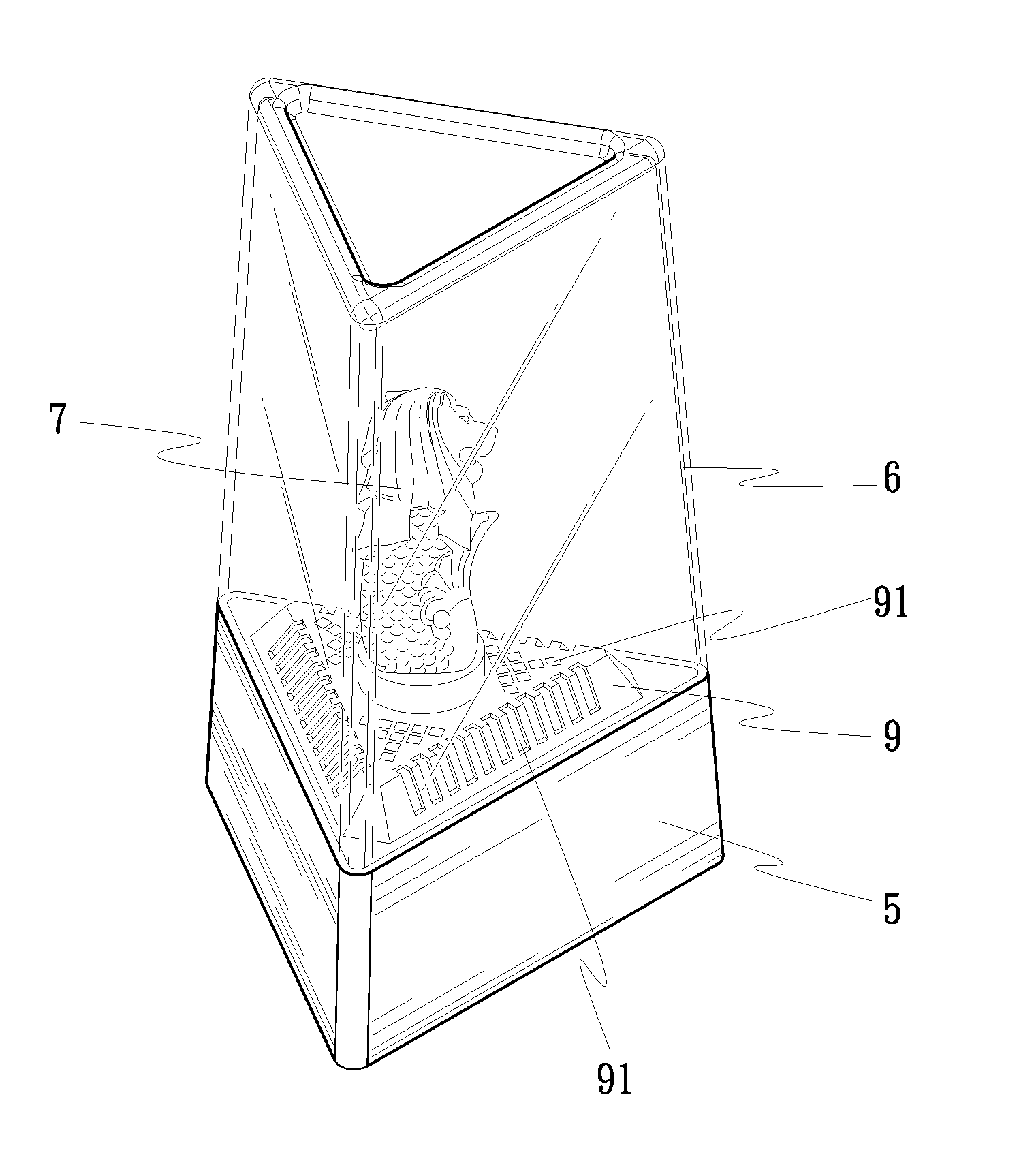
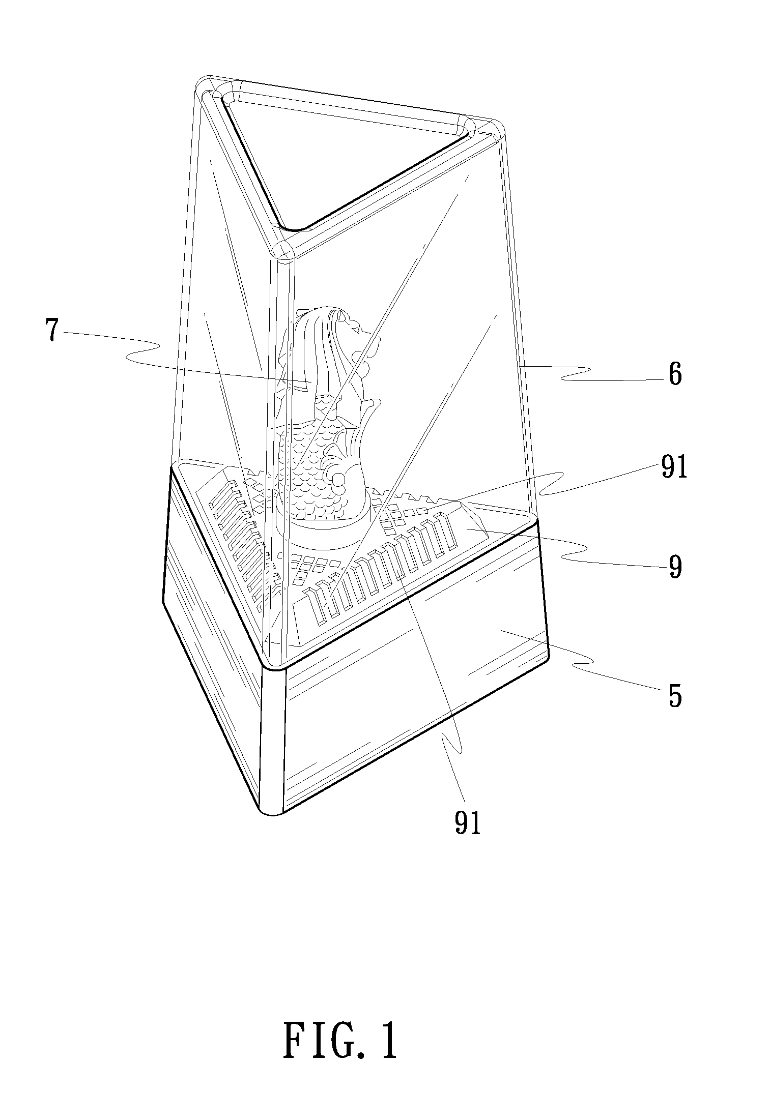
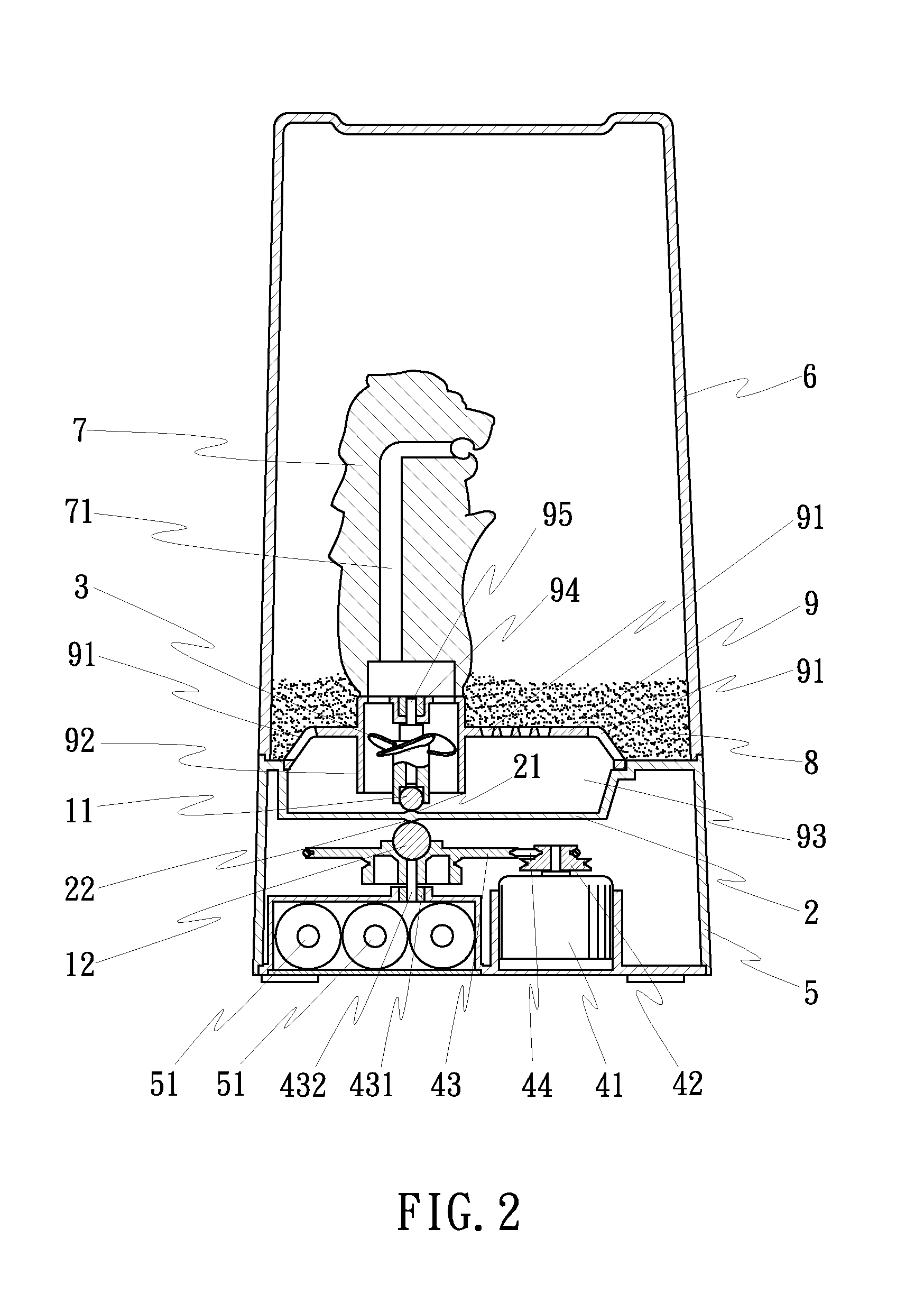
[0020]Referring to FIGS. 1˜5, a magnetic attraction type motion display toy in accordance with the present invention is shown comprising at least one set of magnets 11 and 12, a non-ferromagnetic spacer board 2, a rotary member 3 (that can be a fan blade or rotary table), and a driving source 4.
[0021]The magnets 11 and 12 are respectively arranged at the top and bottom sides relative to the non-ferromagnetic spacer board 2. The magnet 11 that is disposed at the top side of the spacer board 2 works as a passive member. The magnet 12 that is disposed at the bottom side of the spacer board 2 works as an active member. Further, the magnet 12 that is disposed at the bottom side of the spacer board 2 can be driven by the driving source 4. Further, the magnet 11 that is disposed at the top side of the non-ferromagnetic spacer board 2 is fastened to the bottom side of the rotary member 3 by means of an embedding or plugging technique, or with an adhesive.
[0022]The non-ferromagnetic spacer b...
second embodiment
[0037]Further, the ornament 7a of the aforesaid second embodiment is a simple ornament without flow passage. Alternatively, the ornament can be a rotating device or a device with light emitting means.
[0038]Further, a battery 51 is mounted inside the hollow base 5 to provide the motor 41 of the driving source 4 with the necessary working voltage. AC power adapter may be used to provide the necessary working voltage to the driving source 4.
third embodiment
[0039]FIG. 10 is a sectional view of a magnetic attraction type motion display toy in accordance with a According to this embodiment, the motor 41 of the driving source 4 is adapted for rotating the magnet 12 directly, and the ornament 7 has two flow passages 71.
[0040]Further, an axle bearing 94 is provided between the rotary member 3 or 3a and the pan 9 or 9a, and an axle 95 is supported in the axle bearing 94 and inserted through the pan 9 or 9a and connected between the ornament 7 or 7a and the rotary member 3 or 3a. The axle bearing 94 is isolated from the see-through hollow shell 6, assuring smooth rotation of the rotary member 3 or 3a and avoiding leakage. Further, the driven wheel 43 of the driving source 4 is provided with an axle bearing 431 and an axle 432, assuring smooth rotation of the driven wheel 43.
[0041]Further, the see-through hollow shell 6 is made of a transparent material and sealed to the hollow base 5 in a watertight manner. Sound and / or light generating mean...
PUM
 Abstract
Description
Claims
Application Information
 - R&D Engineer
- R&D Manager
- IP Professional
- Industry Leading Data Capabilities
- Powerful AI technology
- Patent DNA Extraction
Browse by: Latest US Patents, China's latest patents, Technical Efficacy Thesaurus, Application Domain, Technology Topic.
© 2024 PatSnap. All rights reserved.Legal|Privacy policy|Modern Slavery Act Transparency Statement|Sitemap