Packet-Switched Access Networks

a packet switching and access network technology, applied in data switching networks, frequency-division multiplexes, instruments, etc., can solve problems such as unfavorable packet switching, unplanned delay and loss of packets, and inability to perform this frequently (e.g. every few minutes) and achieve the effect of reducing congestion and reducing congestion

Inactive Publication Date: 2009-11-12
KINGS COLLEGE LONDON
View PDF8 Cites 6 Cited by
  • Summary
  • Abstract
  • Description
  • Claims
  • Application Information

AI Technical Summary

Benefits of technology

The present invention provides a method for reducing congestion in a packet-switched access network using a tunnelling-type micro-mobility protocol and a mobility agent. The method involves advertising to mobile nodes which traffic class can use which mobility protocol, and dynamically mapping the traffic class to the mobility protocol based on congestion in the network. This allows for better control over the use of the tunnelling-type micro-mobility protocol and reduces congestion in the network. The method can also include advertising a static mapping between traffic class and mobility protocol or monitoring packet congestion and adjusting the mapping accordingly. The invention can be used in a wireless last-hop type network or a host-based network.

Problems solved by technology

These binding updates can introduce unwanted delays and loss of packets, and thereby degradation in performance from the user's perspective.
Doing this frequently (e.g. every few minutes) is not practical.
However, whilst tunnelling-type micro-mobility protocols address the handover latency problem, we have realised that the use of a bi-directional tunnel is very likely to increase packet delay in the access network itself.
This results in packet congestion around the MAPs leading to bottlenecks within the access network.
This overcomes the disadvantage of shortest path routing where the certain shortest paths are quickly congested, resulting in lower network capacity.
However, since tunnelling-type micro-mobility protocols breaking the routing across the access network in two, under utilized paths are created within the network which cannot be used; this reduces the capacity of the access network.
Furthermore any potential benefits of using QoS routing in such a network may not be fully realised.
Such delays can be particularly detrimental to delay sensitive packet traffic (carrying real-time data such as voice for example).

Method used


Image

  • Packet-Switched Access Networks
  • Packet-Switched Access Networks
  • Packet-Switched Access Networks

Examples


Embodiment Construction

)

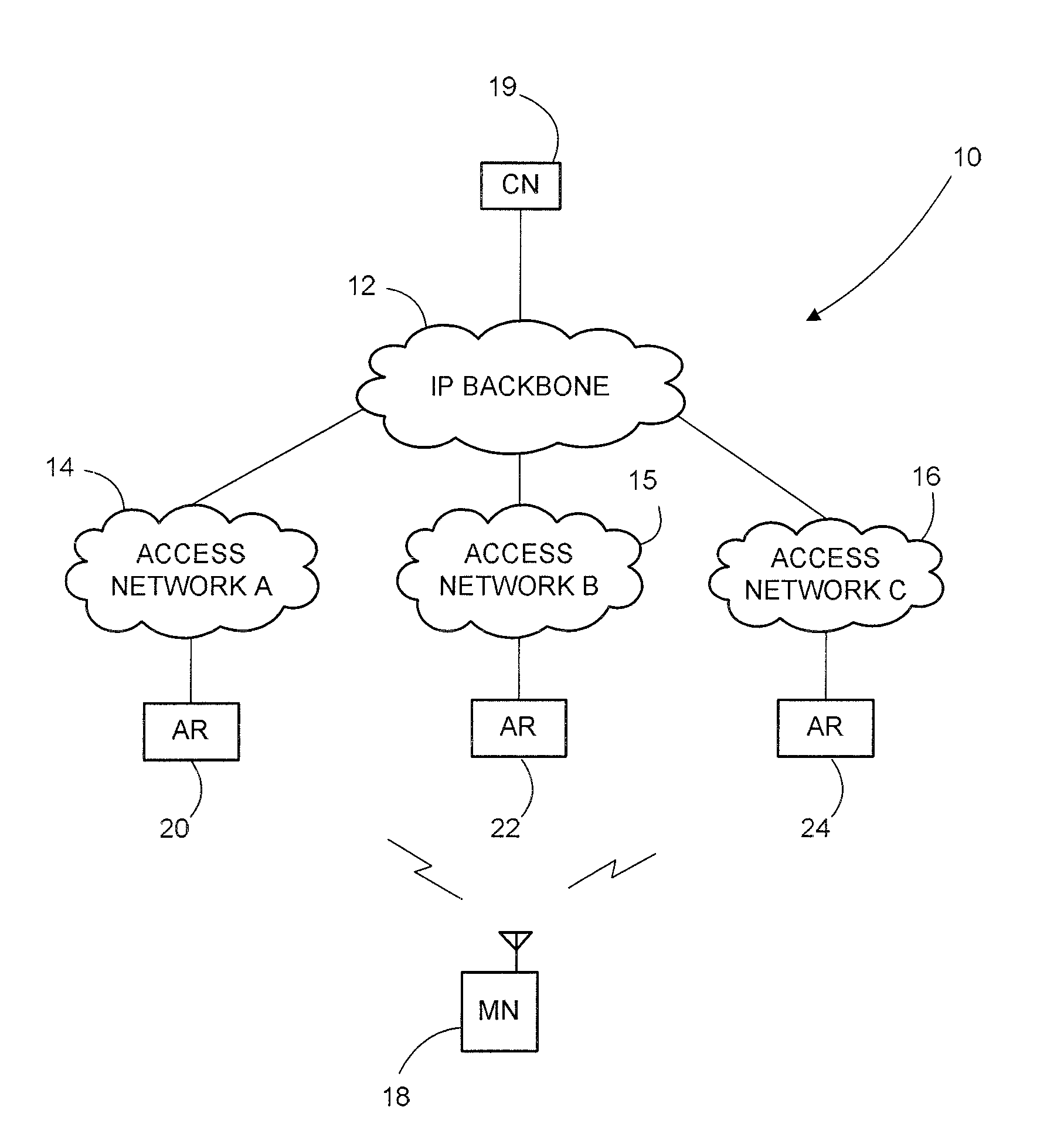
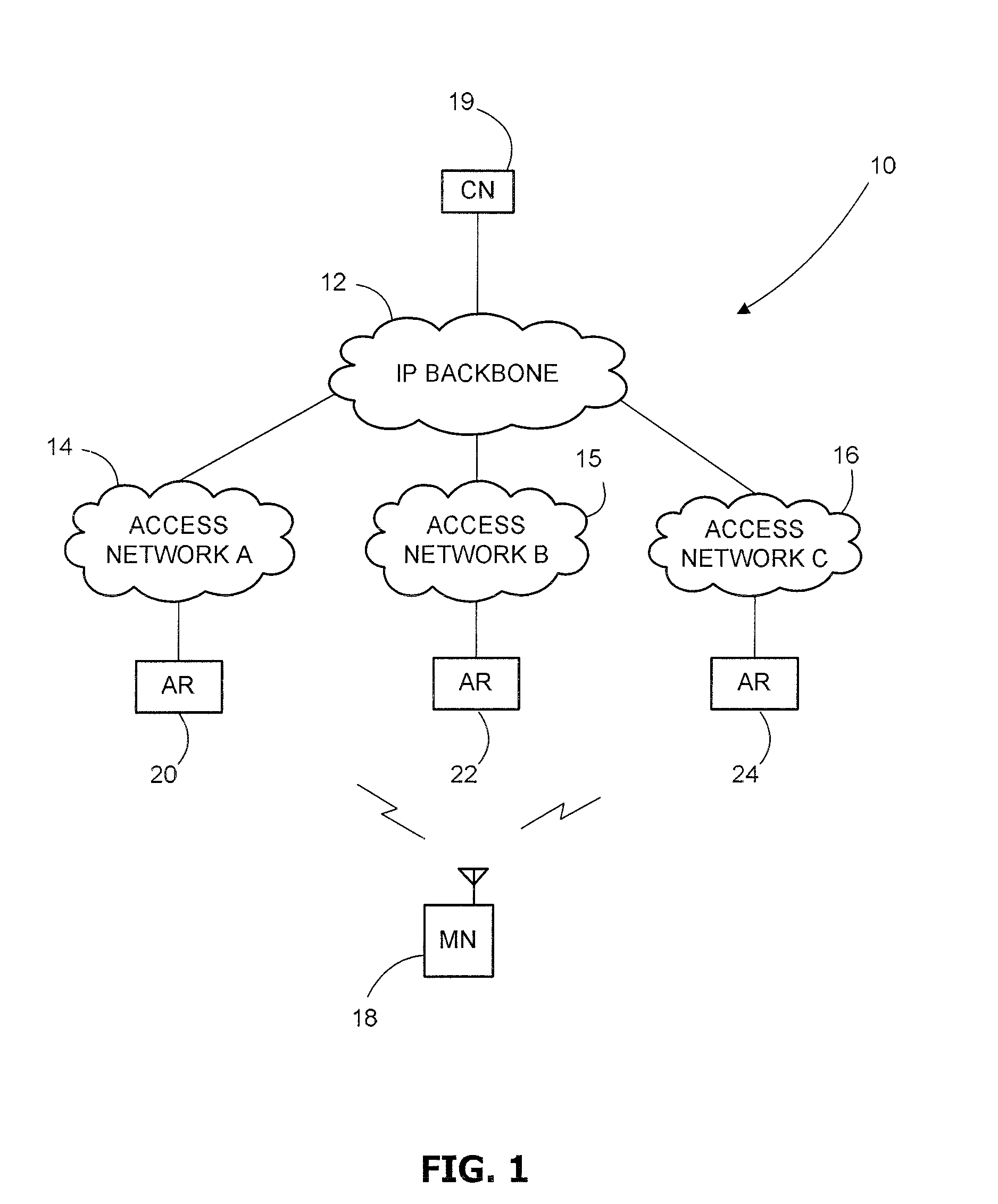
[0066]Referring to FIG. 1 an IP-based (IPv4 or IPv6 or a mixture thereof may be used in any of the networks mentioned herein) network environment generally identified by reference numeral 10 comprises an IP backbone 12 having a number of interconnected routers that provide access for network nodes to data and services stored on remote servers for example. As such the IP backbone 12 may form part of the Internet. In this embodiment any of three IP-based access networks 14, 15, 16 provide access for a wireless mobile node (MN) 18 to the IP backbone 12, although there may be any number of access networks and mobile nodes of course. The access networks 14, 15, 16 may be an IP-based cellular network (such as 3GPP Release 5 or 6, UMTS Long Term Evolution (LTE) or any future IP-enabled cellular network) or the combination of an ISP and a number of WLAN routers for example. Access to the IP backbone 12 enables the MN 14 to communicate with a correspondent node (CN) 19. The CN 19 may be a m...


PUM


Abstract

In a packet-switched access network using a tunnelling-type micro-mobility protocol whereby packets are caused to flow through at least one mobility agent located in said access network, a method of reducing congestion at and / or in routers near said mobility agent, which method comprises the steps of causing packet traffic of a first class to use said tunnelling-type micro mobility protocol and packet traffic of a second class to use another mobility protocol, whereby packet traffic of said second class is routed across said access network away from said mobility agent.

Description

CROSS REFERENCE TO RELATED APPLICATION(S)[0001]This application claims foreign priority to United Kingdom Patent Application Serial Number 07 251 43.2 filed Dec. 24, 2007, the entire disclosure of which is herein incorporated by reference.BACKGROUND OF THE INVENTION[0002]1. Field of the Invention[0003]The present invention relates to a method of reducing congestion at and / or in routers near a mobility agent in a packet-switched access network, to a method of operating a mobile node, to a method of operating a network node, to a packet-switched wireless access network for performing the method, to a mobile node for use in the method, to a method of manufacturing such a mobile node, and to a tunnelling type micro-mobility protocol message for use in a method as aforesaid.[0004]2. Description of Related Art[0005]Mobility at the network layer is concerned with maintaining the routability of packet data to and from a mobile node when that mobile node moves away from its home access netwo...

Claims


Application Information

Patent Timeline
Patent Type & Authority Applications(United States)
IPC IPC(8): H04L12/56H04L12/26
CPCH04L45/125H04L45/302H04L47/10H04L47/11H04L47/122H04W40/02H04L47/2433H04L47/2441H04L47/2475H04L2212/0025H04W28/10H04L47/14H04L2212/00H04W28/02H04L12/56H04W8/04
Inventor AGHVAMI, ABDOL HAMIDPANGALOS, PAUL ANTHONYAUDSIN, DEV PRAGAD
Owner KINGS COLLEGE LONDON
Why Eureka
Try Eureka