Wireless base station device, terminal, and wireless communication method

a wireless base station and terminal technology, applied in the field of wireless base station devices, terminals, wireless communication methods, can solve the problems of increasing the processing delay associated with them, and achieve the effects of reducing the processing time required to control the spatial division multiplexing transmission, simplifying the allocation process, and simplifying the wireless base station devi

Active Publication Date: 2009-11-12
PANASONIC CORP
View PDF12 Cites 70 Cited by
  • Summary
  • Abstract
  • Description
  • Claims
  • Application Information

AI Technical Summary

Benefits of technology

[0010]This structure allows to select an optimum transmit weight from among those generated according to different transmit weight generation algorithms. The optimum transmit weight is optimum for the spatial correlation conditions between the terminals detected by the channel information at the time of spatial division multiplexing transmission to the terminals. This achieves spatial division multiplexing transmission robust to the spatial correlation conditions between the terminals, thereby simplifying the conventional allocation process based on the spatial correlation coefficient. As a result, the wireless base station device can be simplified and the processing time required to control the spatial division multiplexing transmission can be reduced. Thus, the wireless base station device, the terminal, and the wireless communication method of the present invention can increase the system capacity by spatial division multiplexing transmission.

Problems solved by technology

This complicates both the detection of a spatial correlation coefficient and the allocation of the terminals to be connected by spatial division multiplexing, thereby increasing the processing delay associated therewith.

Method used


Image

  • Wireless base station device, terminal, and wireless communication method
  • Wireless base station device, terminal, and wireless communication method
  • Wireless base station device, terminal, and wireless communication method

Examples


first embodiment

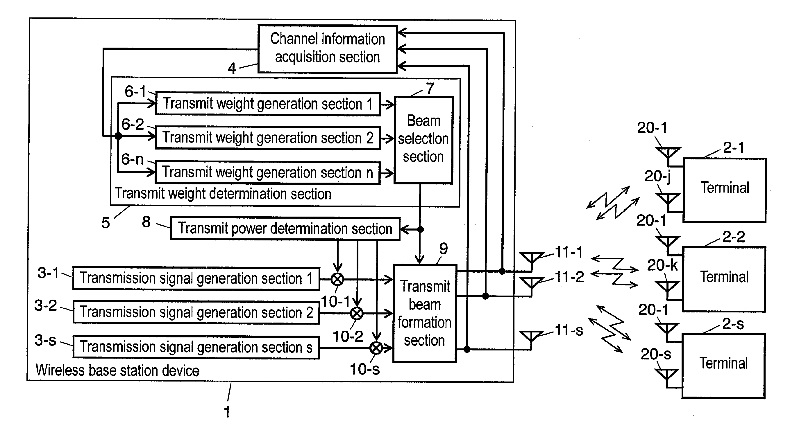
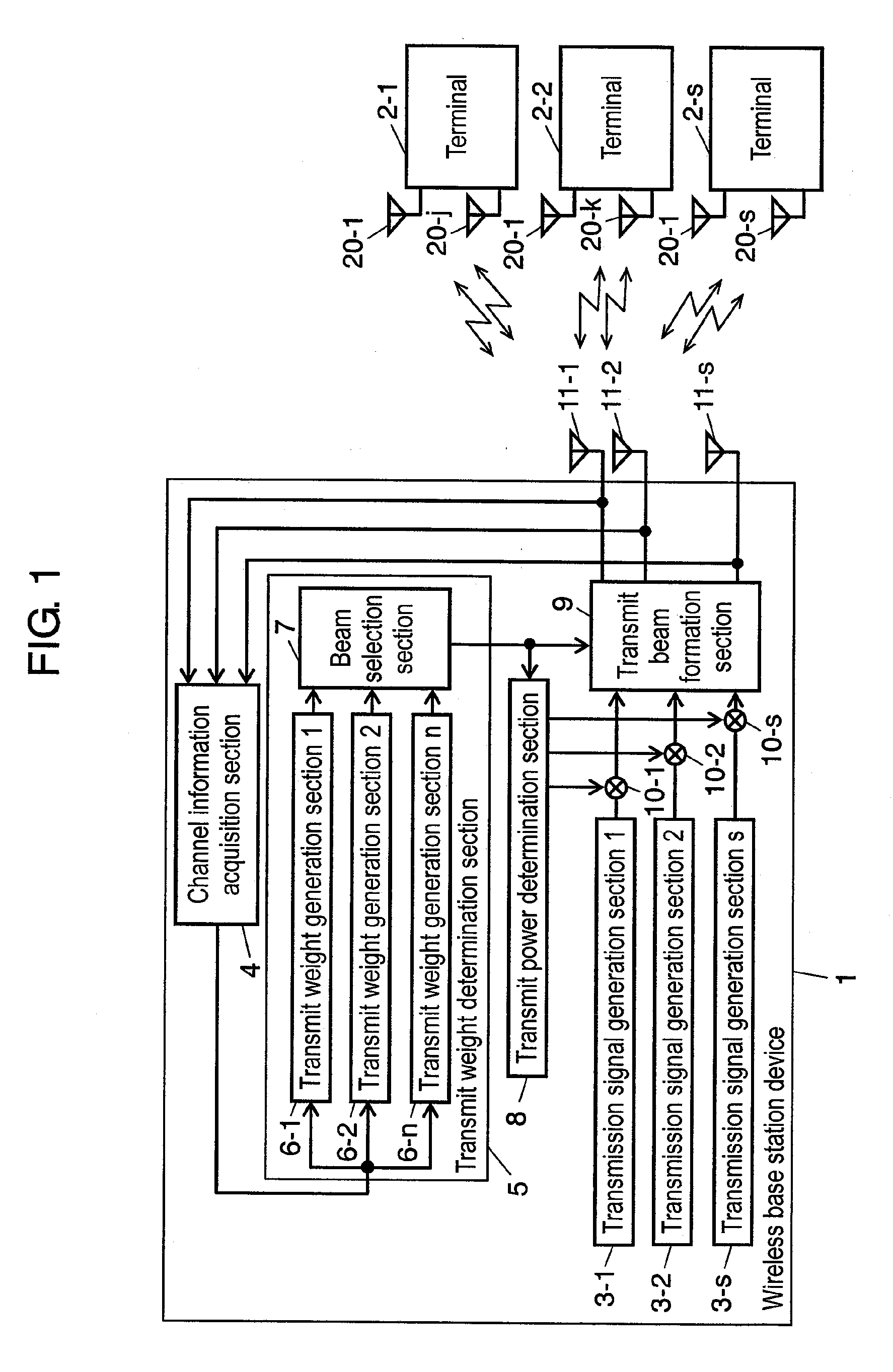
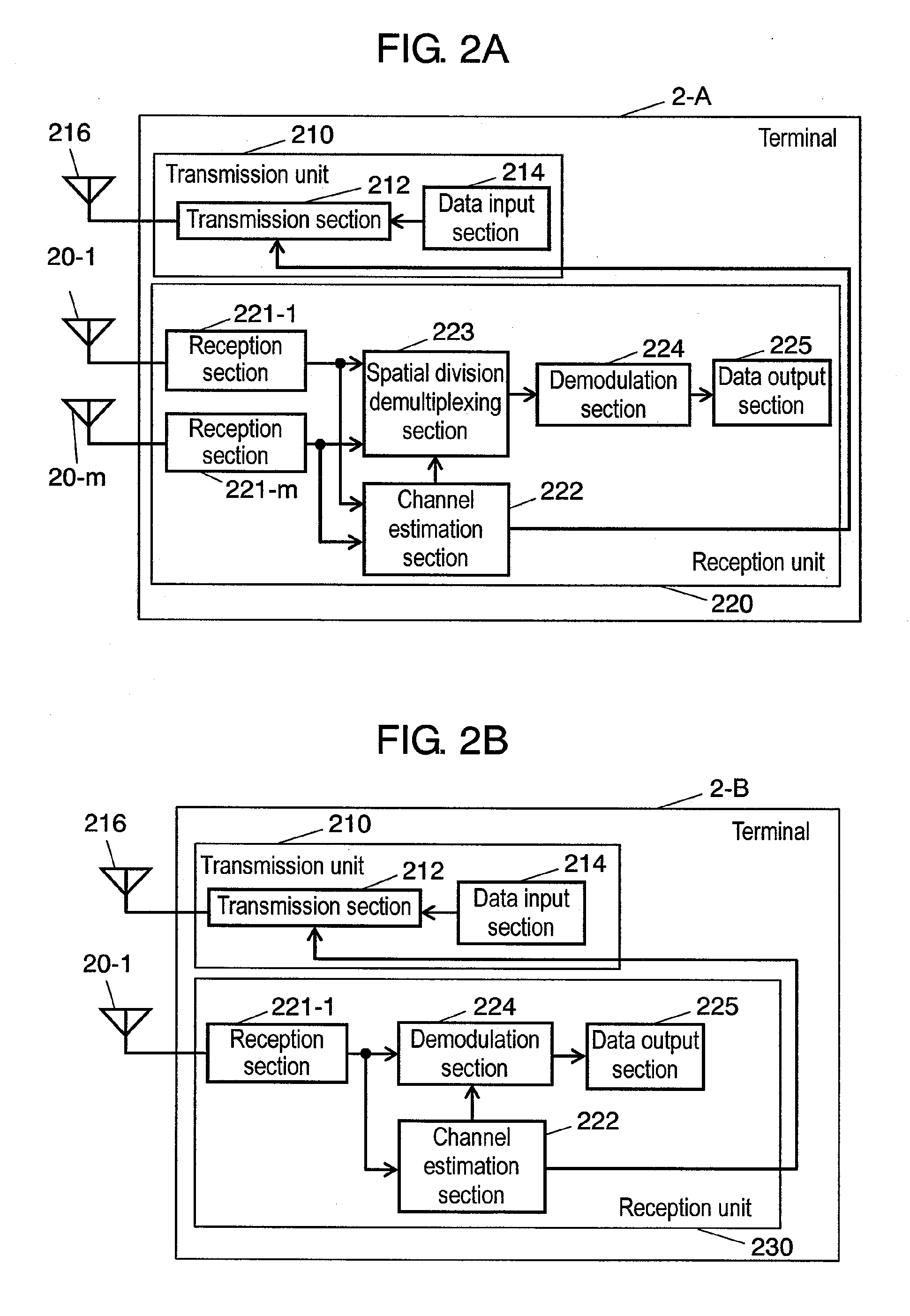
[0053]The structure of a wireless base station device and terminals of a first embodiment of the present invention is shown in FIG. 1. In FIG. 1, terminals 2-1 to 2-s each have antennas 20-1 to 20-j, 20-1 to 20-k, and 20-1 to 20-s, respectively, but may each have only one antenna. FIGS. 2A and 2B show detailed diagrams of a terminal having a plurality of antennas and a terminal having a single antenna, respectively, on the receiving side.

[0054]FIG. 1 is a diagram of wireless base station device 1 and terminals 2-1 to 2-s according to the first embodiment of the present invention. The following description of the present embodiment assumes a case where wireless base station device 1 transmits “Ns” spatial streams to “s” terminals where Ns≧s and Ns is a natural number. The transmission from wireless base station device 1 to terminals 2-1 to 2-s is hereinafter referred to as “downlink”.

[0055]In FIG. 1, wireless base station device 1 of the first embodiment of the present invention incl...

second embodiment

[0222]Wireless base station device 100 of a second embodiment of the present invention is shown in FIG. 11.

[0223]Wireless base station device 100 differs from wireless base station device 1 of the first embodiment in that there is provided selector switch section 107-a instead of beam selection section 7 and there is further provided selector switch section 107-b between channel information acquisition section 4 and transmit weight generation sections 6-1 to 6-n. From a functional point of view, device 100 differs from device 1 in that channel information acquisition section 4 has not only the conventional function of extracting channel information but also the function of controlling selector switch sections so as to select the optimum transmit weight generation section 6 based on the extracted channel information.

[0224]On the other hand, selector switch sections 107-a and 107-b are associated with each other. For example, when selector switch section 107-b selects transmit weight ...

third embodiment

[0236]Wireless base station device 1-A and terminal 2-C of a third embodiment of the present invention are shown in FIG. 12 and FIG. 13, respectively. Wireless base station device 1-A of the present embodiment differs from wireless base station device 1 of the first embodiment in that there are provided separation algorithm acquisition section 400 and beam selection section 401. Separation algorithm information acquisition section 400 acquires spatial division demultiplexing algorithm information transmitted from terminal 2-C. Beam selection section 401 selects one of the outputs of transmit weight generation sections 6-1 to 6-n based on the spatial division demultiplexing algorithm information. Terminal 2-C of the present embodiment differs from terminal 2-A of the first embodiment in that terminal 2-C includes spatial division demultiplexing algorithm storage section 300 and transmission section 212-A. Spatial division demultiplexing algorithm storage section 300 stores spatial di...


PUM


Abstract

A wireless base station device includes a plurality of transmit weight generation sections and a beam selection section. The transmit weight generation sections generate pieces of transmit weight information used for spatial division multiplexing transmission according to different algorithms. The pieces of transmit weight information are generated based on channel information on a plurality of terminals each having one or more antennas with which the wireless base station device performs spatial division multiplexing transmission. The beam selection section selects one of the pieces of transmit weight information generated.

Description

[0001]THIS APPLICATION IS A U.S. NATIONAL PHASE APPLICATION OF PCT INTERNATIONAL APPLICATION PCT / JP2006 / 307613.TECHNICAL FIELD[0002]The present invention relates to a wireless base station device which performs spatial division multiplexing transmission with terminals; to the terminals which support spatial division multiplexing transmission; and to a method of wireless communication between the wireless base station device and the terminals.BACKGROUND ART[0003]In recent years, wireless communication has been increasingly required to have higher capacity and higher speed, so that it has been actively studied to further improve utilization efficiency of finite frequency resources. Of the various methods developed so far, the use of the spatial domain is drawing attention.[0004]One of the spatial domain techniques is to use adaptive array antennas (adaptive antennas). In this technique, a received signal is multiplied by a weighting coefficient to adjust its amplitude and phase. This ...

Claims


Application Information

Patent Timeline
Patent Type & Authority Applications(United States)
IPC IPC(8): H04W74/00H04J99/00
CPCH04B7/0695H04W52/42H04B7/0697
Inventor KISHIGAMI, TAKAAKIYOMO, HIDEKUNI
Owner PANASONIC CORP
Why Eureka
Try Eureka